


34 SMART-MR10/15 User Manual Rev 5
Chapter 2 Installation
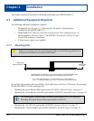
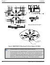
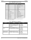
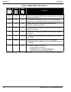
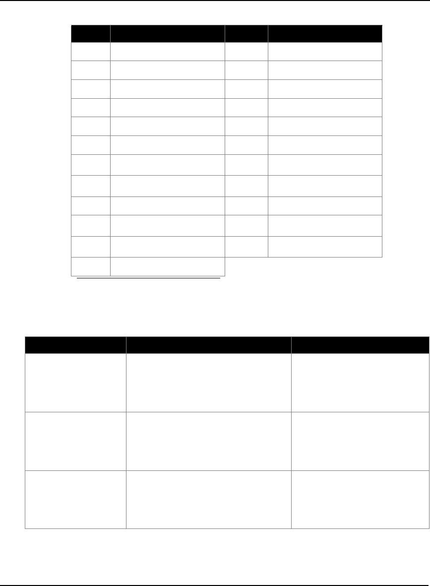
Table 3: SMART-MR10 Connector Pin-Out
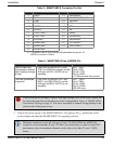
Table 4: SMART-MR10 Use of MODE Pin
Pin Use Pin Use
1 PWR+ 13 RESERVED
2 PWR- 14 CHASSIS GROUND
3 CAN1- 15 SIGGND1
4 CAN1+ 16 MKI
5 TXD2 17 PPS
6 RXD2 18 ER
7
TXD1/TXD1+
a
19
MODE
a
a. The SMART-MR10/15 is RS-232/RS-422-selectable through pin 19
MODE, as shown in Table 4.
8
RTS1/AUXTX/TXD1-
a
20 RESERVED
9 SIGGND2 21 RESERVED
10 RESERVED 22
CTS1/AUXRX/RXD1-
a
11 RESERVED 23
RXD1/RXD1+
a
12 RESERVED
MODE Pin Result Pin-out
Open Pins 8 and 22 provide RS-232 access to
the AUX port TX and RX lines. COM1
flow control and COM1 RS-422 TX- and
RX- signals are not available in this
configuration.
Pin 7: TXD1
Pin 8: AUXTX
Pin 22: AUXRX
Pin 23: RXD1
(2 COM ports, no flow control)
Tied Low (connected to
ground)
Pins 8 and 22 provide TXD1- and
RXD1- for COM1 RS-422, and the AUX
port (AUXRX, AUXTX) is not available.
Pin 7: TXD1+
Pin 8: TXD1-
Pin 22: RXD1-
Pin 23: RXD1+
(RS-422 only)
Tied High (connected
to positive side of
battery through a fuse)
Pins 8 and 22 provide RTS1 and CTS1
for COM1 flow control, and the AUX
port (AUXTX, AUXRX) is not available.
Pin 7: TXD1
Pin 8: RTS1
Pin 22: CTS1
Pin 23: RXD1
(1 COM port with flow control)