


Installation Chapter 2
SMART-MR10/15 User Manual Rev 5 35
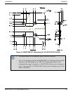
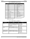
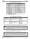
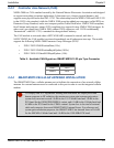
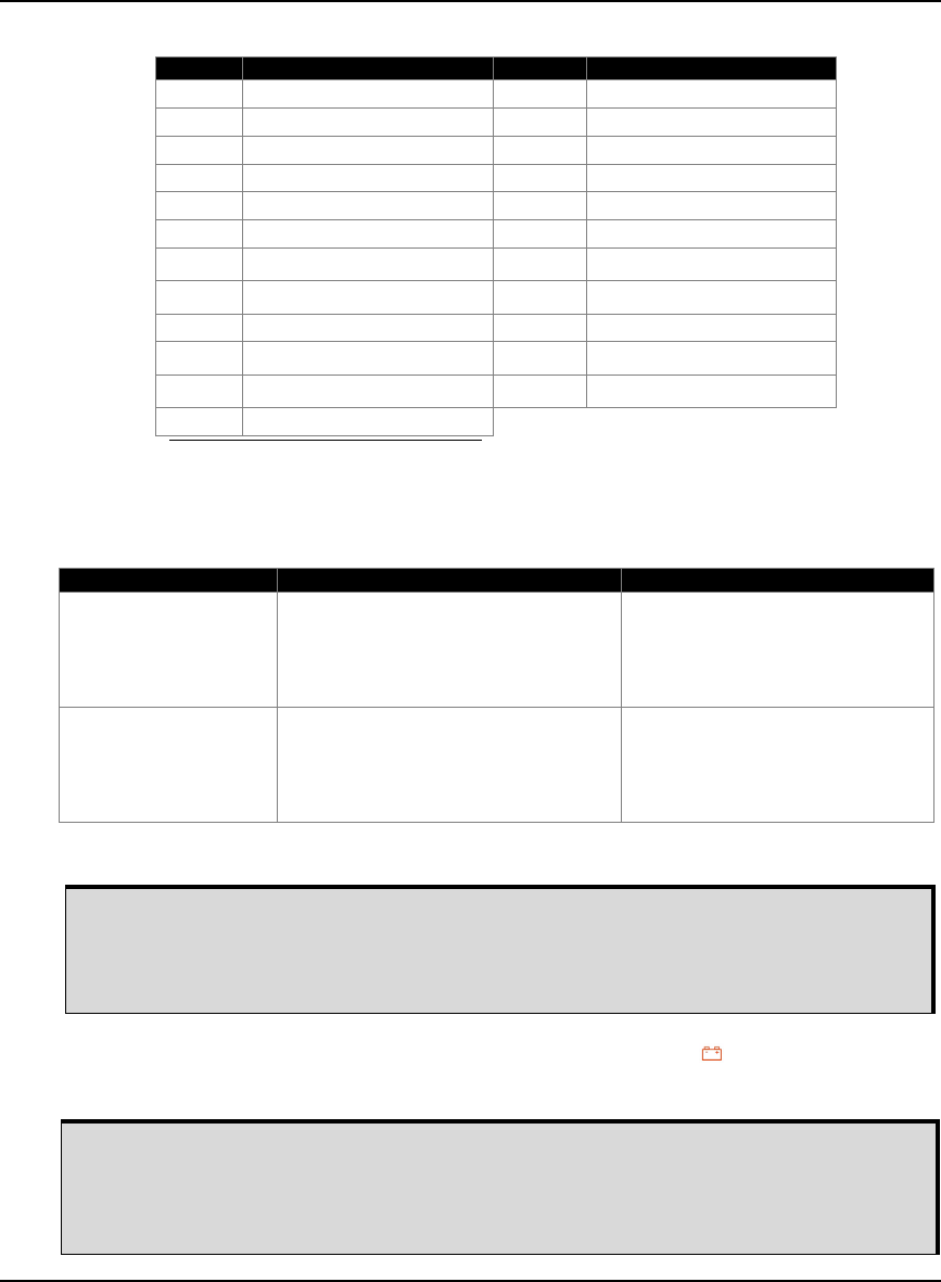
Table 5: SMART-MR15 Connector Pin-Out
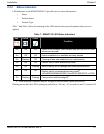
Table 6: SMART-MR15 Use of MODE Pin
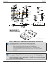
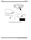
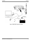
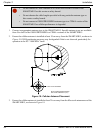
2. Turn on the power supply to the SMART-MR10/15. The power LED on the back of the
receiver lights red when the SMART-MR10/15 is properly powered.
Pin Use Pin Use
1 PWR+ 13 RESERVED
2 PWR- 14 CHASSIS GROUND
3 CAN1- 15 SIGGND1
4 CAN1+ 16 MKI
5 AUXTX 17 PPS
6 AUXRX 18 ER
7
TXD1/TXD1+
a
19
MODE
a
a. The SMART-MR15 is RS-232/RS-422-selectable through pin 19
MODE, as shown in Table 6.
8
RTS1/TXD1-
a
20 RESERVED
9 SIGGND2 21 RESERVED
10 RESERVED 22
CTS1/RXD1-
a
11 RESERVED 23
RXD1/RXD1+
a
12 RESERVED
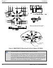
MODE Pin Result Pin-out
Open or tied High
(connected to positive
side of battery through
a fuse)
Pins 8 and 22 provide RTS1 and
CTS1 for COM1 flow control, and the
AUX port (AUXTX, AUXRX) is not
available.
Pin 7: TXD1
Pin 8: RTS1
Pin 22: CTS1
Pin 23: RXD1
(1 COM port with flow control)
Tied Low (connected
to ground)
Pins 8 and 22 provide TXD1- and
RXD1- for COM1 RS-422, and the
AUX port (AUXRX, AUXTX) is not
available.
Pin 7: TXD1+
Pin 8: TXD1-
Pin 22: RXD1-
Pin 23: RXD1+
(RS-422 only)
If the MODE pin is tied high, it must be tied high through a fuse. In this case, MODE can
be tied to the same fuse as the red power lead, as illustrated in Figure 8, SMART-MR10
Streamlined Cabling on page 32. It is never acceptable to connect wiring directly to the
positive side of the power source.
Minimum conductor size for all wiring is 0.5 mm / 20 AWG. While the AMPSEAL
connector can accommodate X mm / 20 AWG wire electrically, in order to ensure IP67
performance, the wire insulation diameter needs to be no less than 2.2 mm / 0.0826
inches.