


5B.20
Section 5B
EFI Fuel System
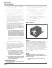
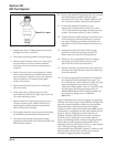
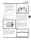
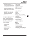
Figure 5B-26. Fuel Pressure Regulator Details.
Service
Depending on the application, the regulator may be
located in the fuel tank along with the fuel pump, or
outside the tank just down line from the pump. The
regulator is a sealed, non-serviceable assembly. If it is
faulty, it must be separated from the base/holder
assembly and replaced as follows:
1. Shut engine off, make sure engine is cool, and
disconnect the negative (-) battery cable.
2. Depressurize fuel system through test valve in
fuel rail (see fuel warning on page 5B.2).
3. Access the regulator assembly as required and
clean any dirt or foreign material away from the
area.
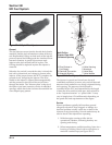
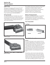
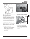
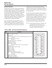
4. External Regulator -
Based upon the style of regulator used: See
Figure 5B-27:
General
The fuel pressure regulator assembly maintains the
required operating system pressure of 39 psi ± 3. A
rubber-fiber diaphragm (see Figure 5B-26) divides the
regulator into two separate sections; the fuel chamber
and the pressure regulating chamber. The pressure
regulating spring presses against the valve holder
(part of the diaphragm), pressing the valve against the
valve seat. The combination of atmospheric pressure
and regulating spring tension equals the desired
operating pressure. Any time the fuel pressure against
the bottom of the diaphragm exceeds the desired (top)
pressure, the valve opens, relieving the excess
pressure, returning the excess fuel back to the tank.
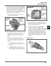
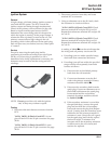
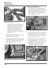
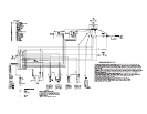
Figure 5B-28. Internal (In-Tank) Regulator and
Base/Holder.
5. Always use new O-Rings and hose clamps when
installing a regulator. A new replacement
regulator will have new O-Rings already
installed. Lubricate the O-Rings (external
regulator) with light grease or oil.
Outlet Port
(To Fuel Rail)
Return Port (To Tank)
Inlet Port
Pressure
Regulating
Spring
Pressure
Regulating
Chamber
Diaphragm
Valve
Valve Seat
Fuel Chamber
a. Remove the two screws securing the
mounting bracket to the regulator housing.
Remove the O-Ring and pull the regulator out
of the housing.
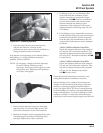
b. Remove the snap ring and remove regulator
from base/holder.
Internal (In-Tank) Regulator -
Remove the three screws securing the retaining
ring and regulator in the base/holder assembly.
Grasp and pull the regulator out of the base/
holder. See Figure 5B-28.
Figure 5B-27. External Regulators and Base/
Holders.