5.13
Section 5
Fuel System and Governor
5
Always use new gaskets when servicing or reinstalling
carburetors. Repair kits are available which include
new gaskets and other components. Service/repair kits
available for Nikki carburetors and affiliated
components are:
Carburetor Repair Kit
Float Kit
High Altitude Kit (1525-3048 m/5,000-10,000 ft.)
High Altitude Kit (Over 3048 m/10,000 ft.)
Solenoid Assembly Kit
Reassembly Procedure
Reassembly is essentially the reverse of the
disassembly procedure. Use new gaskets, springs and
adjusting screws as provided in the carburetor repair
kit. Also use new carburetor and intake manifold
gaskets. Set the idle speed (RPM) adjusting screw (if
equipped) 2-1/4 turns open for initial adjustment and
make final adjustments as described earlier.
Keihin Carburetors (CV17-740)
Float Replacement
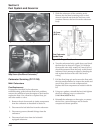
1. Clean the exterior surfaces of dirt or foreign
material before disassembling the carburetor.
Unseat the clamp and disconnect the accelerator
pump hose (if so equipped), from the upper
fitting. Remove the four fuel bowl screws and
carefully separate the fuel bowl from the
carburetor. Do not damage the O-Ring(s).
Transfer any remaining fuel into an approved
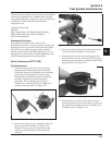
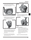
container. Save all parts. See Figure 5-11.
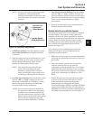
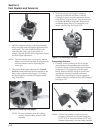
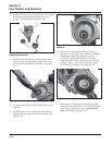
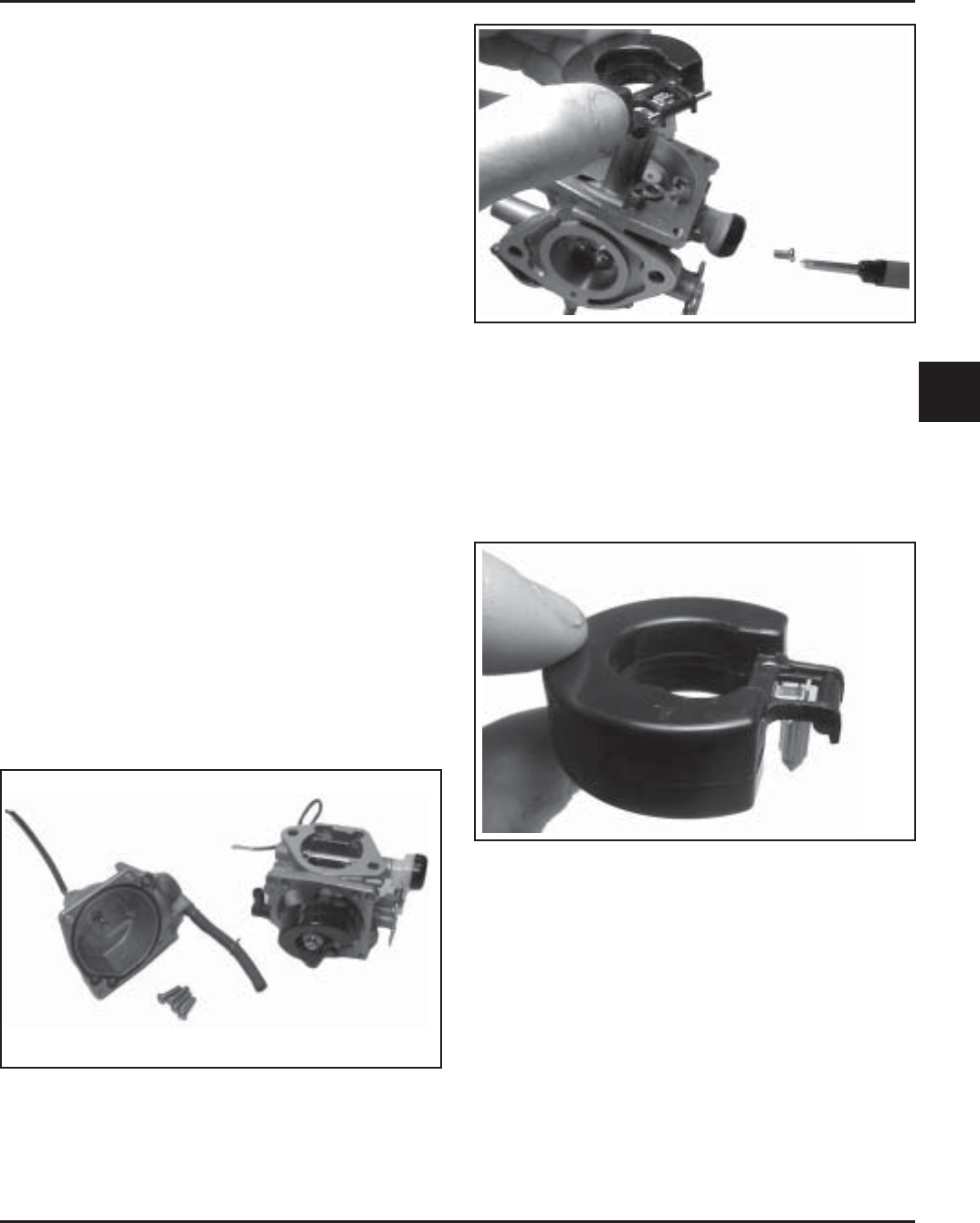
Figure 5-12. Removing Float and Inlet Needle.
3. Clean the carburetor bowl and inlet seat areas as
required, before installation of new parts.
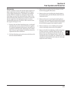
4. Attach the inlet needle to the metal tang of the
float with the wire clip. The formed 90° lip of the
metal tang should point up, with the needle valve
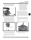
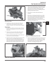
hanging down. See Figure 5-13.
Figure 5-11. Fuel Bowl Removed from Carburetor.
2. Remove the float pin screw and lift out the old
float, pin, and inlet needle. See Figure 5-12.
Discard all of the parts. The seat for the inlet
needle is not serviceable, and should not be
removed.
Figure 5-13. Float and Inlet Needle.
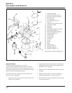
5. Install the float and inlet needle down into the
seat and carburetor body. Insert the new pivot pin
through the float hinge and secure with the new
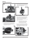
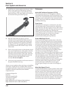
retaining screw. See Figure 5-14.


