8.12
Section 8
Electrical System and Components
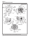
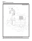
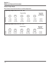
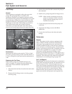
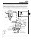
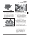
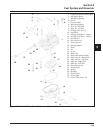
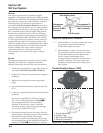
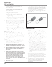
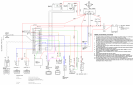
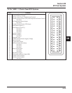
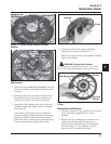
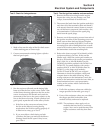
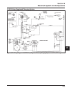
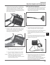
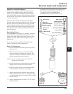
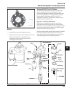
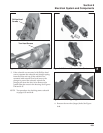
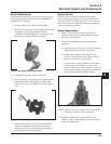
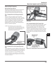
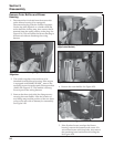
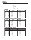
Figure 8-12.
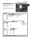
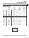
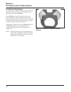
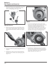
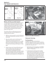
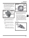
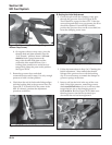
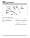
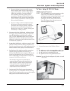
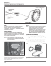
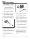
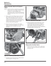
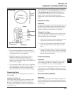
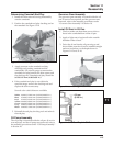
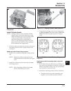
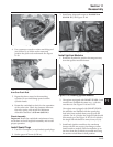
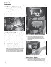
2. Check the SAM part number stamped on the side
of the housing. Verify that you have an analog
SAM (ASAM) Part No. 24 584 10 or lower, not a
digital SAM (DSAM) Part No. 24 584 18 and
higher. Follow sub-step a for testing an ASAM
with this tester. Digital SAM (DSAM) modules
require Tester 25 761 40-S for proper testing.
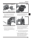
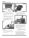
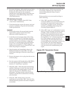
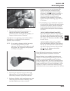
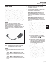
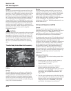
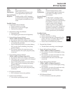
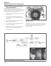
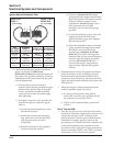
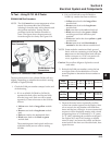
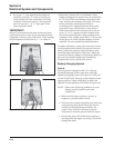
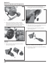
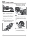
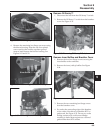
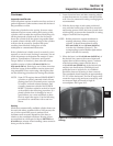
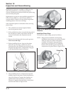
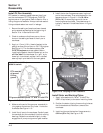
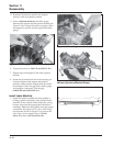
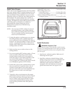
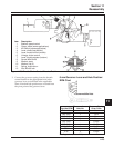
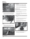
a. Depress the tester button and hold it down.
After approximately four seconds, a
numerical sequence should be displayed,
beginning with 1 or 2 and continuing to 8 or 9,
followed by a letter “P” (pass) or “F” (fail).
See Figures 8-11 and 8-12. Do not release the
tester button until the test cycle completes and
the display goes off*. If you get a “-” sign
instead of the numerical sequence, and /or an
“F” at the end of the cycle, the SAM is
probably bad. Recheck all of the connections,
check the condition of the tester battery** and
repeat the test. If you get the “-” sign and/or
“F” again in the retest, replace that SAM.
*IMPORTANT!
Allow 15-20 seconds for the tester to clear and reset
itself between tests or if the test is interrupted before
completion of the test cycle. Otherwise, a false reading
may be displayed in the form of a “-” or a faint “8”.
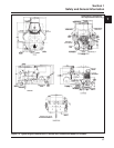
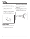
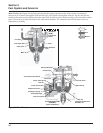
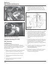
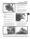
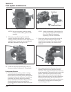
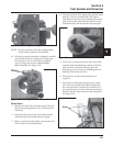
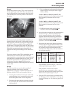
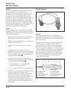
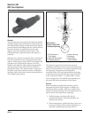
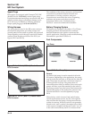
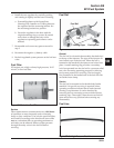
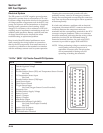
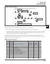
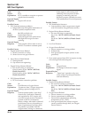
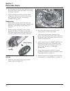
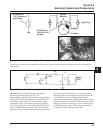
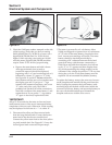
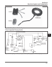
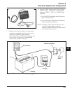
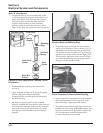
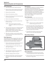
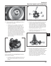
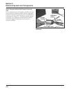
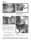
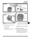
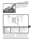
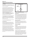
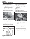
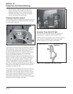
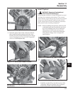
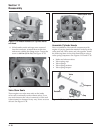
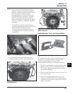
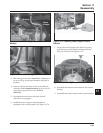
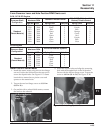
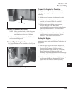
3. Disconnect the yellow and brown tester leads
from the long module leads. Connect the brown
tester lead to the short brown module lead.
Connect the yellow tester lead to the short yellow
(or pink) module lead. See Figure 8-13. Leave the
red and green leads connected. Repeat step 2.
Figure 8-13.
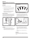
**The tester is powered by a 9-volt battery. Most
SAMs are designed to operate down to a minimum
of 7.25 volts. If the tester battery drops below that
level, incorrect test readings will result. The tester
battery should be checked periodically by
connecting a DC voltmeter between the red and
green lead wires, with the tester connected to a
SAM. Press and hold the test button for a full test
cycle (‘‘F’’ or ‘‘P’’ appears and then display shuts
off), while monitoring the voltage reading on the
voltmeter. If the voltage drops below 7.5 at any time
during the cycle, the 9-volt tester battery must be
replaced. Use an extended life (alkaline) battery.
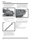
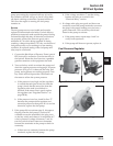
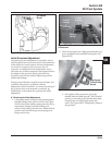
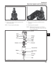
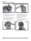
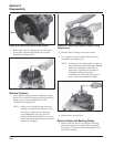
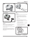
To replace the battery, remove the outer set of screws
on the faceplate and carefully lift the panel from the
body. Unplug the connector and pull battery (with
mounting tape) off the back of the tester. Attach the
connector to the new battery and mount the battery to
the case with double-backed tape. Reinstall the
faceplate and secure with the four screws.