


10.11
Section 10
Inspection and Reconditioning
10
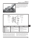
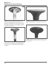
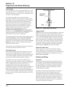
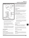
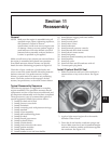
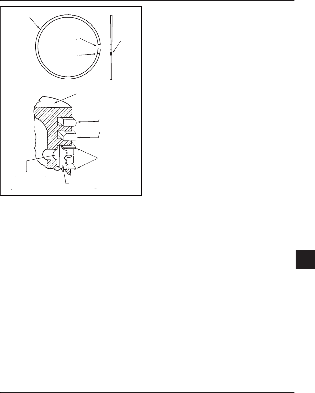
Figure 10-12. Piston Ring Installation.
1. Oil Control Ring (Bottom Groove): Install the
expander and then the rails. Make sure the ends
of the expander are not overlapped.
2. Middle Compression Ring (Center Groove):
Install the center ring using a piston ring
expander tool. Make sure the “identification”
mark is up or the dykem stripe (if contained) is to
the left of the end gap.
3. Top Compression Ring (Top Groove): Install the
top ring using a piston ring expander. Make sure
the “identification” mark is up or the dykem
stripe (if contained), is to the left of the end gap.
Connecting Rods
Offset, stepped-cap connecting rods are used in all
these engines.
Inspection and Service
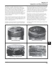
Check the bearing area (big end) for excessive wear,
score marks, running and side clearances (refer to
Section 1, “Specifications, Tolerances, and Special
Torque Values”). Replace the rod and cap if scored or
excessively worn.
Service replacement connecting rods are available in
STD crankpin size and 0.25 mm (0.010 in.) undersize.
The 0.25 mm (0.010 in.) undersized rods have an
identification marking on the lower end of the rod
shank. Always refer to the appropriate parts
information to ensure that correct replacements are
used.
Hydraulic Lifters
Inspection
Check the base surface of the hydraulic lifters for wear
or damage. If the lifters need to be replaced, apply a
liberal coating of Kohler lubricant (see Section 2) to
the base of each new lifter before it is installed.
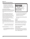
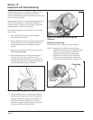
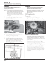
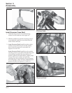
“Bleeding” the Lifters
To prevent a possible bent push rod or broken rocker
arm, it is important to “bleed” any excess oil out of
the lifters before they are installed.
1. Cut a 50-75 mm (2-3 in.) piece from the end of an
old push rod and chuck it in a drill press.
2. Lay a rag or shop towel on the table of the drill
press and place the lifter, open end up, on the
towel.
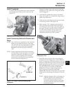
3. Lower the chucked push rod until it contacts the
plunger in the lifter. Slowly “pump” the plunger
two or three times to force the oil out of the feed
hole in the side of the lifter.
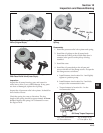
Oil Pan Assembly
Inspection
Inspect the oil seal in the oil pan and remove it if it is
worn or damaged. Refer to ‘‘Install Oil Seal in Oil
Pan’’ in Section 11 for new oil seal installation.
Inspect the main bearing surface for wear or damage
(refer to Section 1, “Specifications, Tolerances, and
Special Torque Values”). Replace the oil pan assembly
if required.
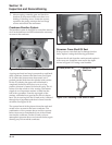
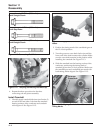
Governor Gear Assembly
Inspection
Inspect the governor gear teeth. Replace the gear if it
is worn, chipped, or if any teeth are missing. Inspect
the governor weights. They should move freely in the
governor gear.
Center
Compression
Ring
Piston Ring
End Gap
Identification
Mark
Dykem
Stripe
Piston
Top
Compression
Ring
Rails
Expander
Oil Control Ring
(Three-piece)