5B.4
Section 5B
EFI Fuel System
During certain operating periods such as cold starts,
warm up, acceleration, etc., an air/fuel ratio richer
than 14.7:1 is required and the system operates in an
“open loop” mode. In “open loop” operation the
oxygen sensor output is not used, and the controlling
adjustments are based on the primary sensor signals
and programmed maps only. The system operates
“open loop” whenever the three conditions for closed
loop operation (above) are not being met.
Important Service Notes!
• Cleanliness is essential and must be maintained
at all times when servicing or working on the EFI
system. Dirt, even in small quantities, can cause
significant problems.
• Clean any joint or fitting with parts cleaning
solvent before opening to prevent dirt from
entering the system.
• Always depressurize the fuel system through the
test valve in the fuel rail before disconnecting or
servicing any fuel system components. See fuel
warning on page 5B.2.
• Never attempt to service any fuel system
component while the engine is running or the
ignition switch is "on".
• Do not use compressed air if the system is open.
Cover any parts removed and wrap any open
joints with plastic if they will remain open for
any length of time. New parts should be removed
from their protective packaging just prior to
installation.
• Avoid direct water or spray contact with system
components.
• Do not disconnect or reconnect the main ECU
wiring harness connector or any individual
components with the ignition ‘‘on.’’ This can send
a damaging voltage spike through the ECU.
• Do not allow the battery cables to touch opposing
terminals. When connecting battery cables attach
the positive (+) cable to the positive (+) battery
terminal first, followed by the negative (-) cable to
the negative (-) battery terminal.
• Never start the engine when the cables are loose
or poorly connected to the battery terminals.
• Never disconnect the battery while the engine is
running.
• Never use a quick battery charger to start the
engine.
• Do not charge the battery with the key switch
‘‘on.’’
• Always disconnect the negative (-) battery cable
before charging the battery, and also unplug the
harness from the ECU before performing any
welding on the equipment.
Electrical Components
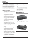
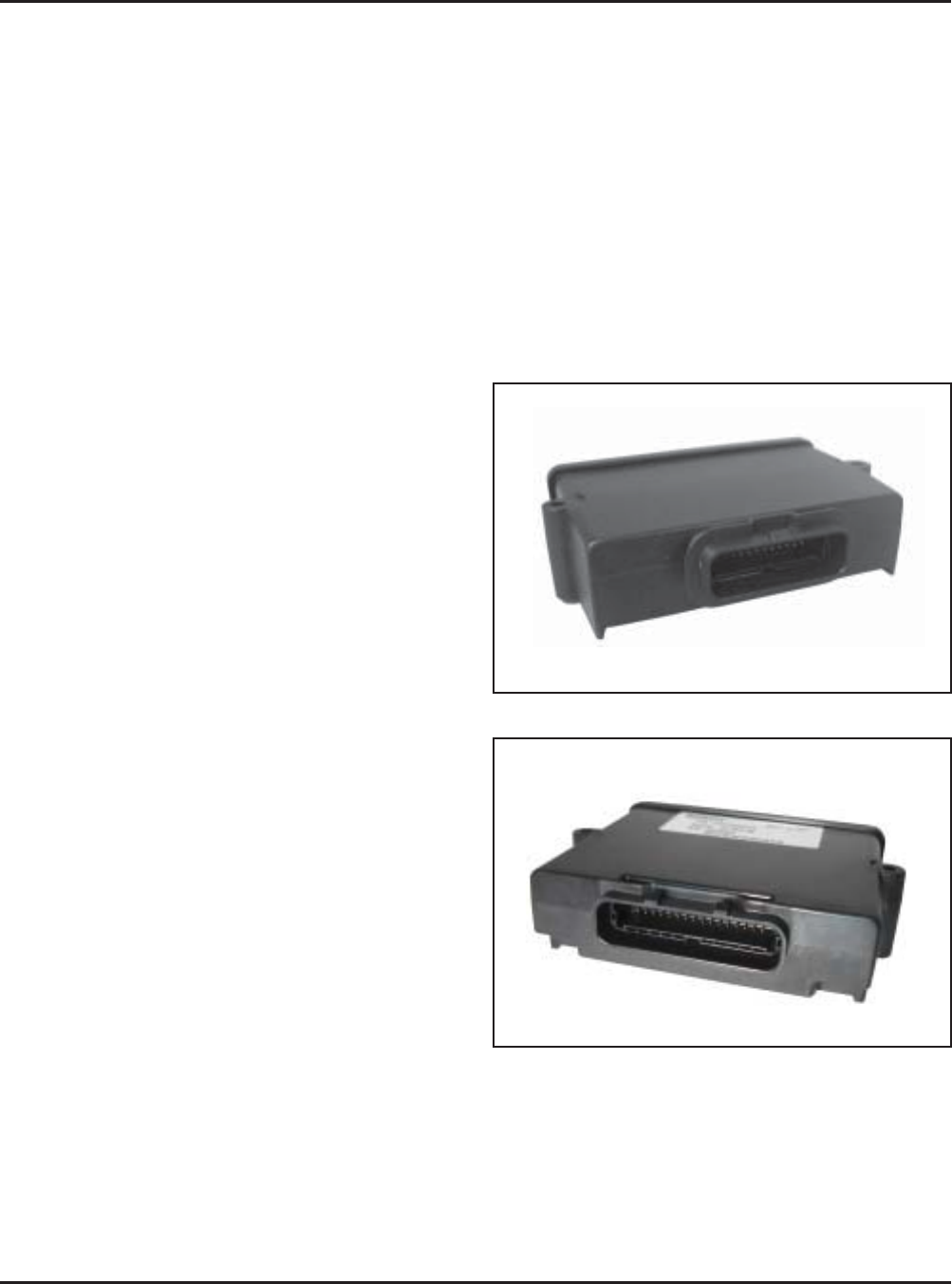
Electronic Control Unit (ECU)
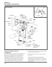
Figure 5B-1. “24 Pin” (MSE 1.0) Plastic-Cased ECU.
Figure 5B-2. “32 Pin” (MSE 1.1) Plastic-Cased ECU.


