


10.5
Section 10
Inspection and Reconditioning
10
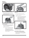
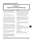
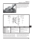
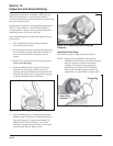
Figure 10-5. Checking Cylinder Head Flatness.
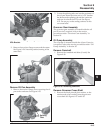
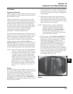
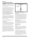
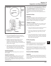
Carefully inspect the valve mechanism parts. Inspect
the valve springs and related hardware for excessive
wear or distortion. Check the valves and valve seat
area or inserts for evidence of deep pitting, cracks, or
distortion. Check clearance of the valve stems in the
guides. See Figure 10-6 for valve details and
specifications.
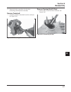
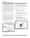
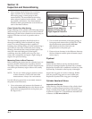
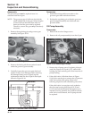
Figure 10-6. Valve Details.
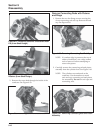
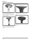
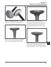
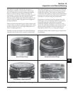
Hard starting, or loss of power accompanied by high
fuel consumption may be symptoms of faulty valves.
Although these symptoms could also be attributed to
worn rings, remove and check the valves first. After
removal, clean the valve heads, faces, and stems with a
power wire brush. Then, carefully inspect each valve
for defects such as warped head, excessive corrosion,
or worn stem end. Replace valves found to be in bad
condition. A normal valve and valves in bad condition
are shown in the accompanying illustrations.
EXHAUST
VALVE
E
G
F
H
D
D
C
A
B
A
B
A
F
E
G
H
INTAKE VALVE
EXHAUST
INSERT
INTAKE
INSERT
A
B
C
D
E
F
G
H
Seat Angle
Insert O.D.
Guide Depth
Guide I.D.
Valve Head Diameter
Valve Face Angle
Valve Margin (Min.)
Valve Stem Diameter
Dimension
89°
36.987/37.013 mm (1.4562/1.4572 in.)
4 mm (0.1575 in.)
7.038/7.058 mm (0.2771/0.2779 in.)
33.37/33.63 mm (1.3138/1.3240 in.)
45°
1.5 mm (0.0591 in.)
6.982/7.000 mm (0.2749/0.2756 in.)
Intake
Exhaust
89°
32.987/33.013 mm (1.2987/1.2997 in.)
6.5 mm (0.2559 in.)
7.038/7.058 mm (0.2771/0.2779 in.)
29.37/29.63 mm (1.1563/1.1665 in.)
45°
1.5 mm (0.0591 in.)
6.970/6.988 mm (0.2744/0.2751 in.)