


11.17
Section 11
Reassembly
11
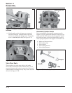
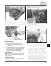
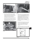
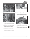
Figure 11-59. Installing Blower Housing.
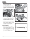
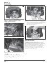
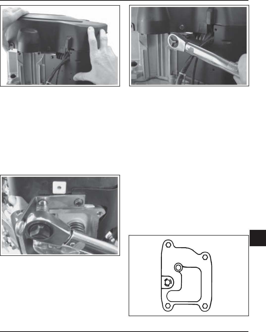
3. Position the outer baffles and secure using the
four hex flange screws (two long, two short) in
the front mounting holes (into cylinder head),
including any lifting strap or attached bracket(s).
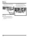
Install the two short screws in the upper
mounting holes of the outer baffles (into the
backing plates). See Figures 11-60 and 11-61. Use
the short screw on the left side to mount the wire
harness bracket. Be sure any leads are routed out
through the proper offsets or notches, so they will
not be pinched between the blower housing and
baffles. See Figures 11-57 through 11-59.
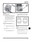
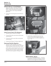
Figure 11-61. Tightening Short Screws for Outer
Baffles.
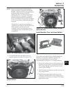
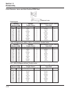
4. Tighten all of the shrouding fasteners. Torque the
blower housing screws to 6.2 N·m (55 in. lb.) in a
new hole, or to 4.0 N·m (35 in. lb.) in a used hole.
Torque the shorter M5 side baffle screws to
4.0 N·m (35 in. lb.). See Figure 11-61. Torque the
M5 side baffle screws (into cylinder head) to
6.2 N·m (55 in. lb.) in a new hole, or to 4.0 N·m
(35 in. lb.) in a used hole. Torque the two lower
M6 baffle mounting screws to 10.7 N·m
(95 in. lb.) in a new hole, or to 7.3 N·m (65 in. lb.)
in a used hole.
5. If the engine had a plastic flywheel that overlaps
the blower housing, reinstall it now. Torque the
mounting screws to 4.0 N·m (36 in. lb.). For a
metal screen, apply Loctite
®
No. 242 to screw
threads and torque the screws to 9.9 N·m
(88 in. lb.).
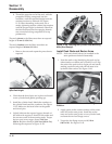
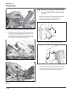
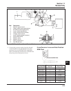
6. Torque the four breather cover screws to 7.3 N·m
(65 in. lb.) in the sequence shown in Figure 11-62.
Figure 11-60. Tightening Outer Baffle Front
Screws.
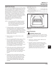
Figure 11-62. Breather Cover Fastener Torque
Sequence.
1
2
3
4