5B.10
Section 5B
EFI Fuel System
Oxygen Sensor
General
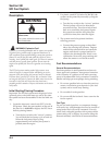
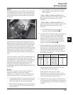
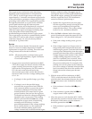
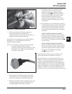
The engine (oil) temperature sensor (Figure 5B-8) is
used by the system to help determine fuel
requirements for starting (a cold engine needs more
fuel than one at or near operating temperature).
Mounted in the oil filter adapter housing, it has a
temperature-sensitive resistor that extends into the oil
flow. The resistance changes with oil temperature,
altering the voltage sent to the ECU. Using a table
stored in its memory, the ECU correlates the voltage
drop to a specific temperature. Using the fuel delivery
“maps”, the ECU then knows how much fuel is
required for starting at that temperature.
Service
The temperature sensor is a sealed, non-serviceable
assembly. A faulty sensor must be replaced. If a blink
code indicates a problem with the temperature sensor,
it can be tested as follows:
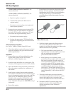
1. Remove the temperature sensor from the adapter
housing and cap or block the adapter hole.
2. Wipe the sensor clean and allow it to reach room
temperature (20°C, 68°F).
3. Unplug the main harness connector from the
ECU.
4. With the sensor still connected, check the
temperature sensor circuit resistance between the
#6 and #4 pin terminals (see chart on page 5B.26
(24 pin) or 5B.29 (32 pin) for pin positions). The
value should be 2375-2625
ΩΩ
ΩΩ
Ω.
5. Unplug the sensor from the wire harness and
check the sensor resistance separately. Resistance
value should again be 2375-2625
ΩΩ
ΩΩ
Ω.
a. If the resistance is out of specifications,
replace the temperature sensor.
b. If it is within specifications, proceed to Step 6.
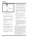
6. Check the circuits (input, ground), from the main
harness connector to the sensor plug for
continuity, damage, etc. Connect one ohmmeter
lead to pin terminal #6 in the main harness
connector (as in step 4). Connect the other lead to
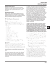
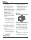
terminal #1 in the sensor plug (see diagram).
Continuity should be indicated. Repeat the test
between pin terminal #4 and terminal #2 in the
sensor plug.
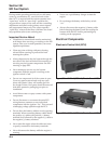
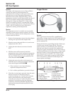
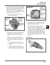
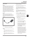
Figure 5B-9. Oxygen Sensor.
General
The oxygen sensor functions like a small battery,
generating a voltage signal to the ECU based upon the
difference in oxygen content between the exhaust gas
and the ambient air.
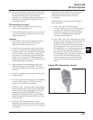
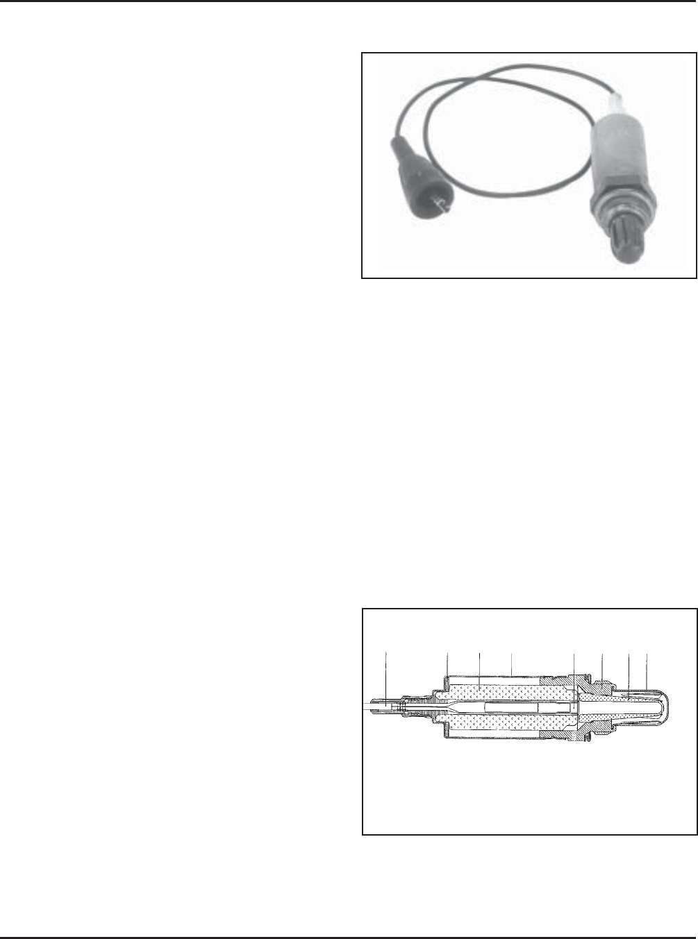
The tip of the sensor, protruding into the exhaust gas,
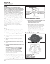
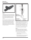
is hollow (see cutaway Figure 5B-10). The outer
portion of the tip is surrounded by the exhaust gas,
with the inner portion exposed to the ambient air.
When the oxygen concentration on one side of the tip
is different than that of the other side, a voltage signal
between 0.2 and 1.0 volts is generated between the
electrodes and sent to the ECU. The voltage signal
tells the ECU if the engine is straying from the ideal
14.7:1 fuel mixture, and the ECU then adjusts the
injector pulse accordingly.
1
2
3
4
5
6
7
8
1. Connection Cable
2. Disc Spring
3. Ceramic Support Tube
4. Protective Sleeve
5. Contact Element
6. Sensor Housing
7. Active Ceramic Sensor
8. Protective Tube
Figure 5B-10. Cutaway of Oxygen Sensor.


