


5B.6
Section 5B
EFI Fuel System
General
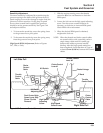
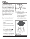
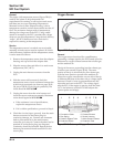
The engine speed sensor is essential to engine
operation; constantly monitoring the rotational speed
(RPM) of the crankshaft. A ferromagnetic 60-tooth ring
gear with two consecutive teeth missing is mounted
on the flywheel. The inductive speed sensor is
mounted 1.5 ± 0.25 mm (0.059 ± 0.010 in.) away from
the ring gear. During rotation, an AC voltage pulse is
created within the sensor for each passing tooth. The
ECU calculates engine speed from the time interval
between the consecutive pulses. The two-tooth gap
creates an interrupted input signal, corresponding to
specific crankshaft position (84° BTDC) for cylinder
#1. This signal serves as a reference for the control of
ignition timing by the ECU. Synchronization of the
inductive speed pickup and crankshaft position takes
place during the first two revolutions each time the
engine is started. The sensor must be properly
connected at all times. If the sensor becomes
disconnected for any reason, the engine will quit
running.
Service
The engine speed sensor is a sealed, non-serviceable
assembly. If “Fault Code” diagnosis indicates a
problem within this area, test and correct as follows.
1. Check the mounting and air gap of the sensor. It
must be 1.5 mm ± 0.25 mm (0.059 ± 0.010 in.).
2. Inspect the wiring and connections for damage or
problems.
3. Make sure the engine has resistor type spark
plugs.
4. Disconnect the main harness connector from the
ECU.
5. Connect an ohmmeter between the #9 and #10 pin
terminals.
See chart on page 5B.26 or 5B.29, according to
ECU style. A resistance value of 750-1000
ΩΩ
ΩΩ
Ω at
room temperature (20°C, 68°F) should be
obtained. If resistance is correct, check the
mounting, air gap, toothed ring gear (damage,
run-out, etc.), and flywheel key.
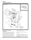
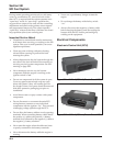
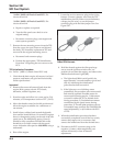
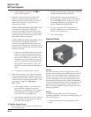
6. Disconnect the speed sensor connector from the
wiring harness. It is the connector with one heavy
black lead (see Figure 5B-4). Viewing the
connector as shown (dual aligning rails on top),
test resistance between the terminals indicated. A
reading of 750-1000
Ω Ω
Ω Ω
Ω should again be obtained.
Figure 5B-4. Speed Sensor Connector.
7. a. If the resistance is incorrect, remove the screw
securing the sensor to the mounting
bracket and replace the sensor.
b. If the resistance in step 5 was incorrect, but
the resistance of the sensor alone was correct,
test the main harness circuits between the
sensor connector terminals and the
corresponding pin terminals (#9 and #10) in
the main connector. Correct any observed
problem, reconnect the sensor, and perform
step 5 again.
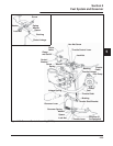
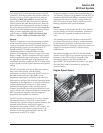
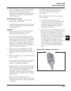
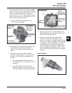
Throttle Position Sensor (TPS)
Dual Aligning Rails
Test Terminals
Corresponds
To #10 Pin
Terminal In Main
Connector
Corresponds To
#9 Pin Terminal In
Main Connector
1
2
3
4
1. Throttle Valve Shaft
2. Resistor Track
3. Wiper Arm With Wiper
4. Electrical Connection
Figure 5B-5. Throttle Position Sensor Details.