5.17
Section 5
Fuel System and Governor
5
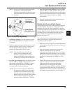
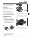
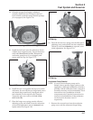
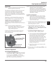
Figure 5-26. Installing Fuel Bowl O-Rings.
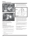
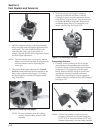
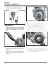
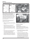
15. Install the fuel bowl onto the carburetor. Secure
with the four original screws. Torque the screws
to 2.5 ± 0.3 N·m (23 ± 2.6 in. lb.). Reattach the
accelerator pump hose (if so equipped), and
secure with the clip. See Figure 5-27.
14. When the proper float height is obtained,
carefully install the new O-Rings for the fuel
bowl and the accelerator pump transfer passage
(if so equipped). See Figure 5-26.
Figure 5-27. Installing Fuel Bowl.
16. Install the new cover gasket and top cover on the
carburetor. Secure with the two large-head screws
and attach the ground lead (if equipped with a
fuel solenoid), to the original screw location.
Torque the top cover screws to 2.5 ± 0.3 N·m
(23 ± 2.6 in. lb.).
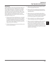
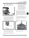
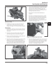
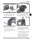
17. Place the longer new spring onto the idle fuel
adjusting screw and install it into the carburetor.
As an initial adjustment, set to 1 turn out from
lightly seated. See Figure 5-28.
Figure 5-28. Installing Idle Fuel Adjusting Screw
and Spring.
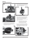
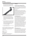
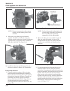
18. Place the shorter new spring onto the idle speed
adjusting screw and install it into the carburetor.
Thread in until 3 or 4 threads are exposed, as an
initial adjustment. See Figure 5-29.
Figure 5-29. Installing Idle Speed Adjusting Screw
and Spring.
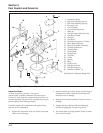
Accelerator Pump Rebuild
NOTE: Access to the accelerator pump can be
limited, due to specific engine options or the
application. Although installation of the kit is
possible with the carburetor intact, removal is
normally necessary and recommended. These
instructions cover installation of the kit
components only. If needed, instructions for
removal and reinstallation of the carburetor
can be found in Sections 9 and 11
respectively.
1. Remove the vacuum hose from the accelerator
pump cover and the carburetor flange fitting.


