


9.15
Section 9
Disassembly
9
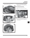
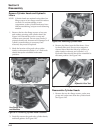
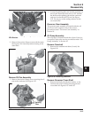
Figure 9-54. Removing Stator.
Remove Oil Pan Assembly
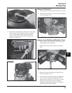
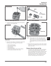
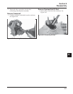
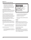
1. Remove the ten hex flange screws securing the oil
pan to the crankcase. See Figure 9-55.
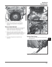
Figure 9-53. Removing Backing Plates and Stator
Wire Bracket.
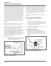
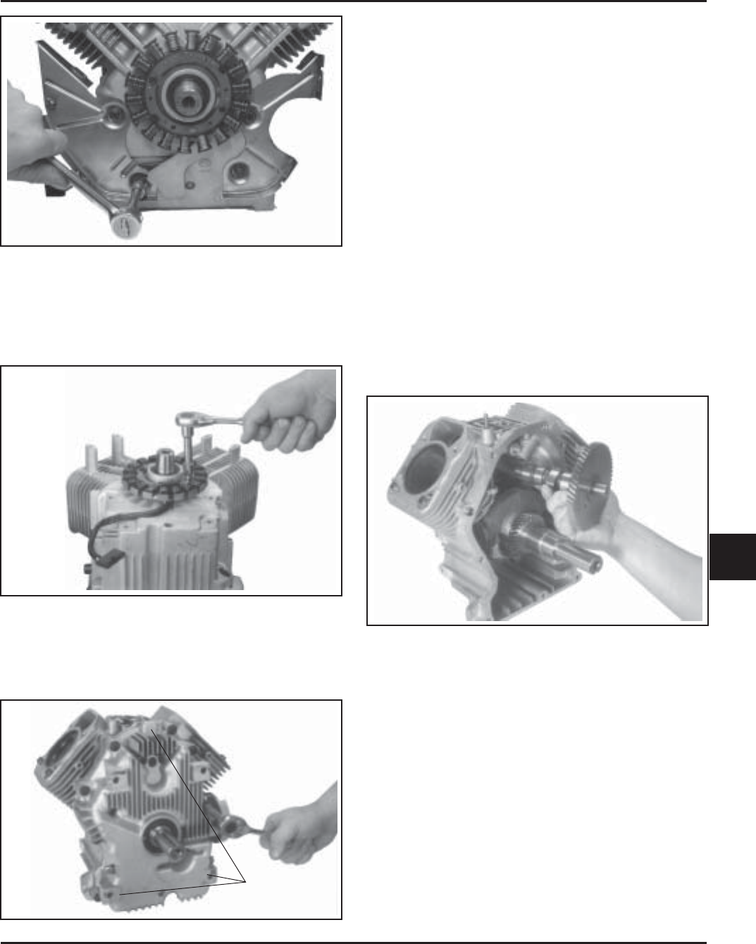
2. Remove the two hex flange screws and the stator.
See Figure 9-54. Note the position/routing of the
stator lead.
Figure 9-55. Removing Oil Pan Fasteners.
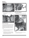
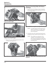
Splitting
Tabs
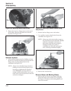
Figure 9-56. Removing Camshaft.
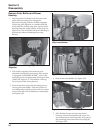
Remove Governor Cross Shaft
1. Remove the hitch pin and plain washer, or the
retainer and nylon washer, from the governor
cross shaft. See Figures 9-57 and 9-58.
2. Locate the splitting tabs cast into the perimeter of
the oil pan. Insert the drive end of a 1/2" breaker
bar between the splitting tab and the crankcase
and turn it to break the RTV seal. See Figure
9-55. Do not pry on the sealing surfaces as this
can cause leaks.
Governor Gear Assembly
The governor gear assembly is located inside the oil
pan. If service is required, refer to the service
procedures under “Governor Gear Assembly” in
Section 10.
Oil Pump Assembly
The oil pump is mounted inside the oil pan. If service
is required, refer to the service procedures under “Oil
Pump Assembly” in Section 10.
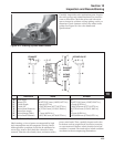
Remove Camshaft
1. Remove the camshaft and shim (if used). See
Figure 9-56.