


5B.17
Section 5B
EFI Fuel System
5B
Ignition System
General
A high-voltage, solid-state, battery ignition system is
used with the EFI system. The ECU controls the
ignition output and timing through transistorized
control of the primary current delivered to the coils.
Based on input from the speed sensor, the ECU
determines the correct firing point for the speed at
which the engine is running. At the proper instant, it
releases the flow of primary current to the coil. The
primary current induces high voltage in the coil
secondary, which is then delivered to the spark plug.
Each coil fires every revolution, but every other spark
is "wasted".
Service
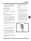
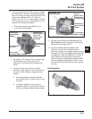
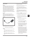
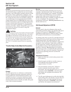
Except for removing the spark plug lead by
unscrewing it from the secondary tower (see Figure
5B-20), no coil servicing is possible. If a coil is
determined to be faulty, replacement is necessary. An
ohmmeter may be used to test the wiring and coil
windings.
Figure 5B-20. Ignition Coil.
NOTE: Do not ground the coils with the ignition
‘‘on,’’ as they may overheat or spark.
Testing
1. Disconnect the main harness connector from the
ECU.
"24 Pin" (MSE 1.0) Plastic-Cased ECU: Locate
pins #22 and #23 in the 24 pin connector. See page
5B.26.
"32 Pin" (MSE 1.1) Plastic Cased ECU: Locate
pins #30 and #31 in the 32 pin connector. See page
5B.29.
2. Disconnect connector from relay and locate
terminal #87 in connector.
3. Using an ohmmeter set on the Rx1 scale, check
the resistance in circuits as follows:
"24 Pin" (MSE 1.0) Plastic-Cased ECU: Check
between terminal #87 and pin #22 for coil #1.
Repeat the test between terminal #87 and pin #23
for coil #2.
"32 Pin" (MSE 1.1) Plastic-Cased ECU: Check
between terminal #87 and pin #30 for coil #1.
Repeat the test between terminal #87 and pin #31
for coil #2.
A reading of 1.8-4.0
ΩΩ
ΩΩ
Ω in each test indicates that
the wiring and coil primary circuits are OK.
a. If reading(s) are not within specified range,
check and clean connections and retest.
b. If reading(s) are still not within the specified
range, test the coils separately from main
harness as follows:
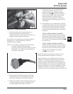
1) Disconnect the red and black primary
leads from the coil terminals.
2) Connect an ohmmeter set on the Rx1
scale to the primary terminals. Primary
resistance should be 1.8-2.5
ΩΩ
ΩΩ
Ω.
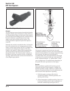
3) Disconnect the secondary lead from the
spark plug. Connect an ohmmeter set on
the Rx10K scale between the spark plug
boot terminal and the red primary
terminal. Secondary resistance should
be 13,000-17,500
ΩΩ
ΩΩ
Ω.
4) If the secondary resistance is not within
the specified range, unscrew the spark
plug lead nut from the coil secondary
tower and remove the plug lead. Repeat
step b. 3, testing from the secondary tower
terminal to the red primary terminal. If
resistance is now correct, the coil is good,
but the spark plug lead is faulty, replace
the lead. If step b. 2 resistance was
incorrect and/or the secondary resistance
is still incorrect, the coil is faulty and
needs to be replaced.