8.13
8
Section 8
Electrical System and Components
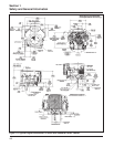
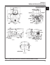
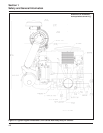
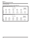
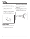
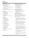
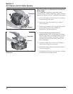
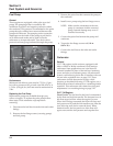
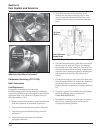
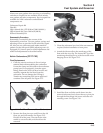
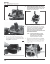
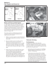
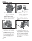
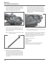
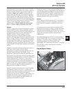
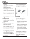
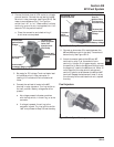
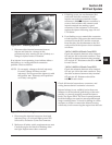
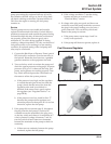
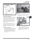
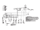
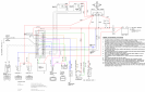
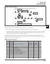
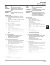
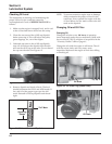
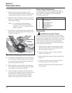
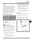
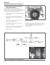
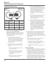
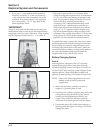
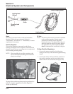
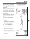
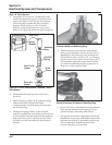
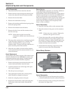
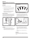
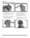
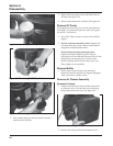
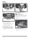
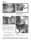
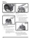
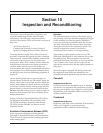
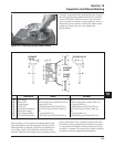
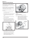
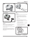
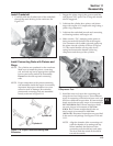
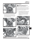
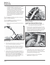
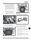
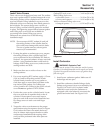
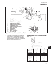
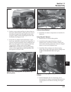
Figure 8-14. Connected Tester Leads.
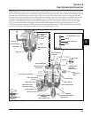
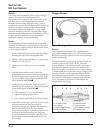
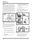
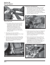
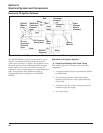
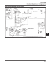
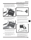
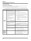
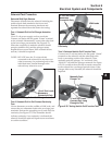
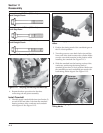
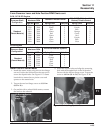
The test procedure for twin cylinder SAMs will vary
slightly, depending on whether the module is analog
(ASAM) or digital (DSAM).
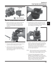
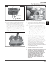
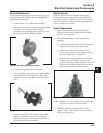
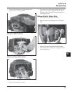
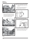
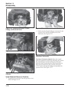
1. Check the SAM part number stamped on the end
of the housing.
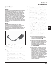
a. If it is an ASAM (24 584 09 or 24 584 10),
separate the short yellow and brown leads
from the long ones. Each set will be tested
separately. Connect the tester to the SAM as
follows:
• Yellow tester lead to long yellow module
lead.
• Brown tester lead to long brown module
lead.
• Red tester lead to the red module lead.
• Black tester lead to the black or green
module lead.
The remaining tester leads (pink and brown
with black band) are not used for testing
ASAMs.
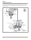
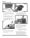
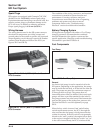
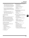
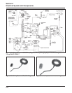
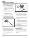
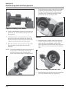
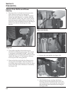
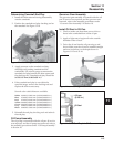
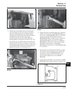
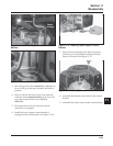
b. If it is a DSAM (all except 24 584 09 or
24 584 10), connect the tester as follows:
• Yellow tester lead to the long yellow
module lead.
• Brown tester lead to the long brown
module lead.
• Red tester lead to the red module lead.
• Black tester lead to the green or black
module ground lead with the eyelet
#
terminal.
• Pink tester lead to the short yellow or pink
module lead.
• Brown tester lead with black band or
terminal to the short brown module lead.
#
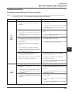
NOTE: Some modules contain two black ground
leads, with one containing a white stripe. Do
not connect to the black/white lead with the
bullet connector or a “Fail” test result will
occur, regardless of actual condition.
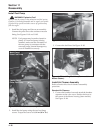
Caution: Do not allow alligator clip leads to touch
each other.
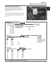
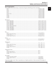
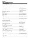
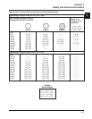
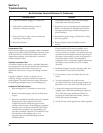
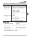
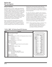
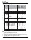
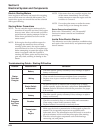
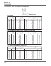
2. Recheck the SAM part number, noting the last
two digits. Refer to the table below or on the
tester faceplate to determine the test number to
be used.
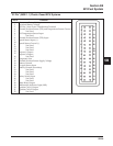
To Test – Using 25 761 40-S Tester
DSAM/ASAM Test Procedure
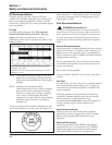
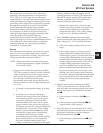
NOTE: The SAM must be at room temperature when
tested. Disconnect all of the SAM leads,
isolating it from the main wiring harness and
the ignition module(s). Testing may be
performed with the module mounted or
loose. The figures show the part removed
from the engine for clarity. See Figure 8-14.
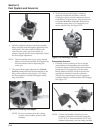
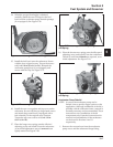
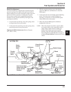
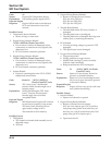
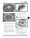
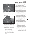
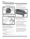
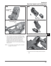
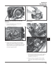
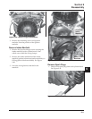
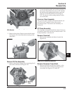
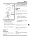
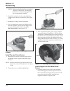
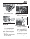
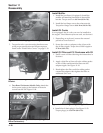
ASAM Module
Test Connections
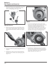
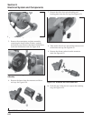
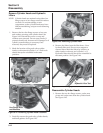
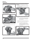
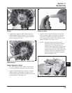
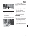
DSAM Module Test
Connections
MAS
.oNtraP
-
8148542
7248542
9148542
8348542
9348542
.oNtseT
5678
MAS
.oNtraP
2148521
9048542
0148542
0348542
1348542
3348542
4348542
2348542
.oNtseT
1234
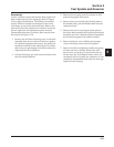
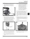
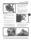
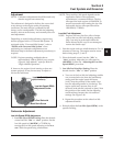
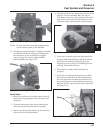
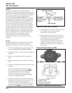
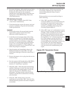
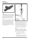
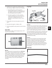
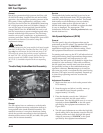
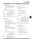
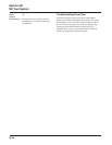
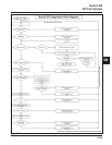
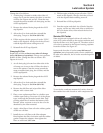
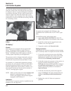
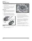
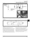
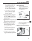
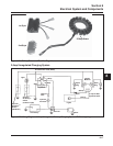
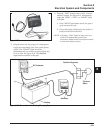
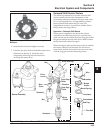
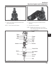
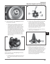
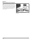
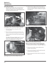
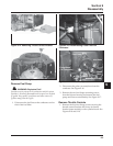
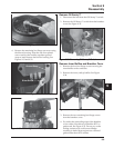
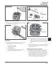
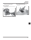
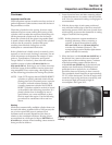
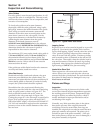
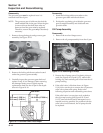
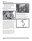
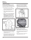
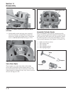
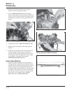
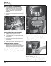
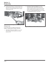
3. Depress the tester button repeatedly until the
correct test number appears on the display. After
a few seconds, the test number will flash three
times and the test will begin. A reverse numerical
sequence will be displayed, starting with a 6 and
progressing down to 1, followed by a “P” (pass)
or “F” (fail), indicating the condition of the part.*
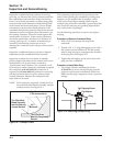
See Figures 8-15 and 8-16. If testing an ASAM,
return to step 1 and move the yellow and brown
tester leads to the short set of module leads, then
repeat the test.