


8.38
Section 8
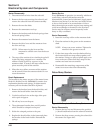
Electrical System and Components
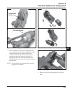
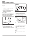
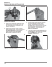
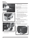
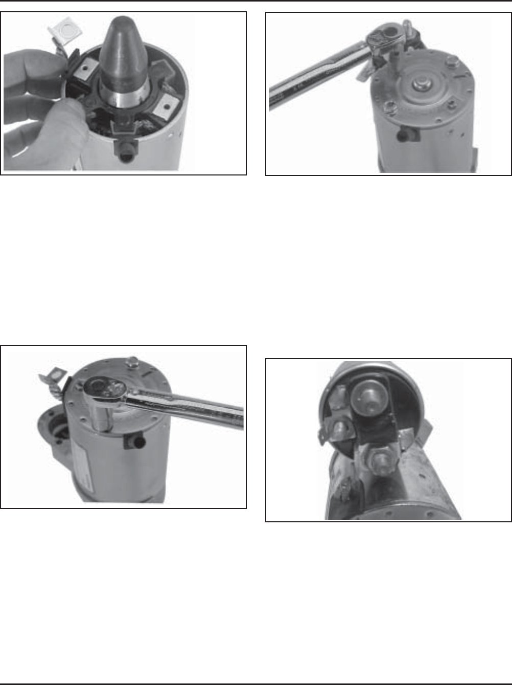
Figure 8-70. Installing Brush Holder Assembly
using Tool with Extension.
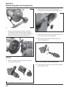
11. Install the end cap onto the armature and frame,
aligning the thin raised rib in the end cap with
the corresponding slot in the grommet of the
positive (+) brush lead.
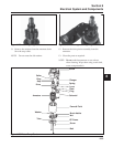
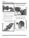
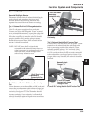
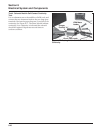
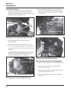
12. Install the two thru bolts, and the two brush
holder mounting screws. Torque the thru bolts to
5.6-9.0 N·m (49-79 in. lb.). Torque the brush
holder mounting screws to 2.5-3.3 N·m
(22-29 in. lb.). See Figures 8-71 and 8-72.
Figure 8-72. Torquing Brush Holder Screws.
13. Hook the plunger behind the upper end of the
drive lever, and install the spring into the
solenoid. Insert the three mounting screws
through the holes in the drive end cap. Use these
to hold the solenoid gasket in position, then
mount the solenoid. Torque the screws to
4.0-6.0 N·m (35-53 in. lb.).
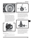
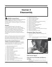
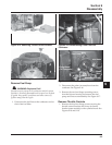
14. Connect the positive (+) brush lead/bracket to the
solenoid and secure with the hex nut. Torque the
nut to 8-11 N·m (71-97 in. lb.). Do not
overtighten. See Figure 8-73.
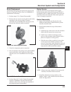
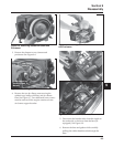
Figure 8-71. Torquing Thru Bolts.
Figure 8-73. Positive (+) Brush Lead Connection.