


5.16
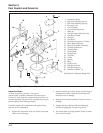
Section 5
Fuel System and Governor
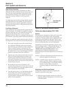
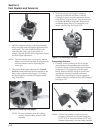
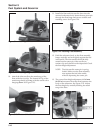
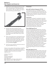
Figure 5-22. Installing Plug into Slow Jet Tube.
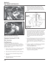
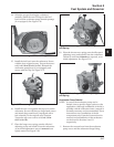
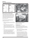
10. Attach the inlet needle to the metal tang of the
float with the wire clip. The formed 90° lip of the
metal tang should point up, with the needle valve
hanging down. See Figure 5-23.
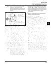
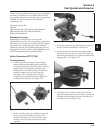
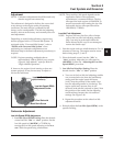
Figure 5-21. Installing Slow Jet.
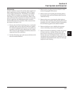
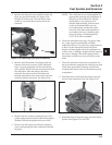
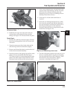
Figure 5-25. Checking Float Height.
Figure 5-23. Float and Inlet Needle.
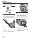
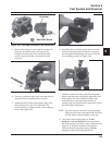
11. Install the float and inlet needle down into the
seat and carburetor body. Insert the new pivot pin
through the float hinge and secure with the new
retaining screw. See Figure 5-24.
Figure 5-24. Installing Float Assembly.
12. Hold the carburetor body so the float assembly
hangs vertically and rests lightly against the fuel
inlet needle. The inlet needle should be fully
seated but the center pin of the needle (on
retainer clip end) should not be depressed. Check
the float height adjustment.
NOTE: The inlet needle center pin is spring
loaded. Make sure the float assembly
rests against the fuel inlet needle,
without depressing the center pin.
13. The correct float height adjustment is 12.0 mm
(0.472 in.) measured from the float bottom to the
body of the carburetor. See Figure 5-25. Adjust
the float height by carefully bending the metal
tang of the float.