


8.5
8
Section 8
Electrical System and Components
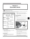
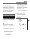
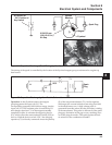
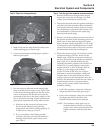
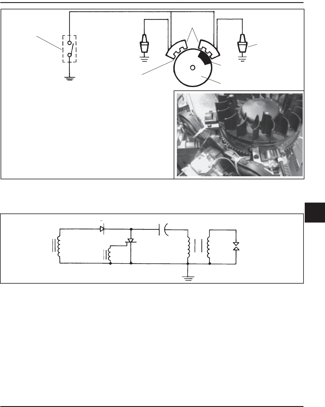
Kill Switch or
‘‘Off’’ Position of
Key Switch
Ignition
Modules
Spark Plug
Magnet
Flywheel
0.28/0.33 mm
(0.011/0.013 in.)
Air Gap
The timing of the spark is controlled by the location of the flywheel magnet group as referenced to engine top
dead center.
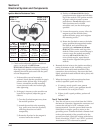
Figure 8-4. Capacitive Discharge (Fixed Timing) Ignition System.
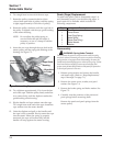
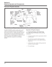
L1
D1
C1
T1
P
S
Spark
Plug
L2
SCS
Figure 8-5. Capacitive Discharge Ignition Module Schematic.
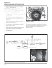
Operation: As the flywheel rotates, the magnet
grouping passes the input coil (L1). The
corresponding magnetic field induces energy into the
input coil (L1). The resultant pulse is rectified by D1
and charges capacitor C1. As the magnet assembly
completes its pass, it activates the triggering device
(L2), which causes the semiconductor switch (SCS) to
turn on. With the device switch “ON,” the charging
capacitor (C1) is directly connected across the primary
(P) of the output transformer (T1). As the capacitor
discharges, the current initiates a fast rising flux field
in the transformer core. A high voltage pulse is
generated from this action into the secondary winding
of the transformer. This pulse is delivered to the spark
plug gap. Ionization of the gap occurs, resulting in an
arc at the plug electrodes. This spark ignites the fuel-
air mixture in the combustion chamber.