


5.20
Section 5
Fuel System and Governor
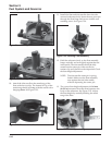
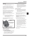
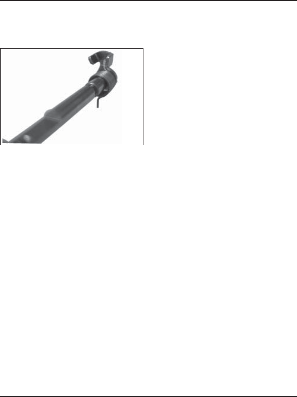
Figure 5-38. Choke Shaft and Spring Details.
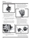
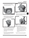
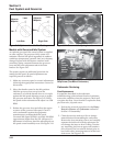
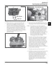
10. Slide the choke shaft and spring, into the
carburetor. Pivot (preload) the shaft and set the
inner leg of the spring, against the formed stop
within the choke lever as originally assembled.
See Figure 5-35. The opposing leg of the spring
must still be between the formed “stops” of the
choke shaft.
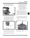
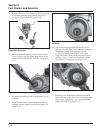
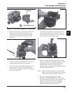
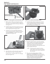
11. Place a drop of the Loctite
®
on the threads of each
new screw. Install the new choke plate to the flat
side of the choke shaft and start the two screws.
The larger cutout must be on the right. Close the
choke and check the plate alignment within the
carburetor throat, then tighten the screws
securely. Do not overtighten.
12. Check for proper operation and free movement of
the parts. Install the new cap.
Always use new gaskets when servicing or reinstalling
carburetors. Repair kits are available which include
new gaskets and other components. Service/repair kits
available for Keihin carburetors and affiliated
components are:
Carburetor Repair Kit
Float Kit
Solenoid Assembly Kit
Accelerator Pump Kit
Choke Repair Kit
High Altitude Kit (1525-3048 m/5,000-10,000 ft.)
High Altitude Kit (Over 3048 m/10,000 ft.)
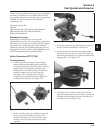
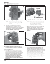
9. Install the new return spring onto the new choke
shaft, so the upper leg of the spring is between
the two formed “stops” on the end of the choke
shaft. See Figure 5-38. Note: Make sure it stays in
this location during the following step.
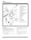
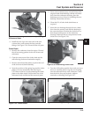
Carburetor
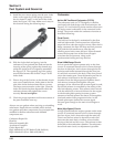
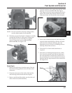
Keihin BK Two-Barrel Carburetor (CV750)
The carburetor used on CV750 engines is a Keihin
two-barrel side draft design with fixed main jets. See
Figure 5-39. A self-relieving choke similar to that used
on single venturi carburetors is also contained in the
design. The circuits within the carburetor function as
described following:
Float Circuit:
The fuel level in the bowl is maintained by the float
and fuel inlet needle. The buoyant force of the float
stops fuel flow when the engine is at rest. When fuel is
being consumed, the float will drop and fuel pressure
will push the inlet needle away from the seat,
allowing more fuel to enter the bowl. When demand
ceases, the buoyant force of the float will again
overcome the fuel pressure, rising to the
predetermined setting and stop the flow.
Slow & Mid-Range Circuit:
At low speeds the engine operates only on the slow
circuit. As a metered amount of air is drawn through
the slow air bleed jets, fuel is drawn through the two
main jets and further metered through the slow jets.
Air and fuel are mixed in the body of the slow jet and
exit to the transfer port. From the transfer port the air
fuel mixture is delivered to the idle progression
chamber. From the idle progression chamber the air
fuel mixture is metered through the idle port
passages. At low idle when the vacuum signal is weak,
the air/fuel mixture is controlled by the setting of the
idle fuel adjusting screws. This mixture is then mixed
with the main body of air and delivered to the engine.
As the throttle plate opening increases, greater
amounts of air/fuel mixture are drawn in through the
fixed and metered idle progression holes. As the
throttle plate opens further the vacuum signal
becomes great enough so the main circuit begins to
work.
Main (High-Speed) Circuit:
At high speeds/loads the engine operates on the main
circuit. As a metered amount of air is drawn through
the four air jets, fuel is drawn through the main jets.
The air and fuel are mixed in the main nozzles and
then enter the main body of airflow, where further
mixing of the fuel and air occurs. This mixture is then
delivered to the combustion chamber. The carburetor
has a fixed main circuit; no adjustment is possible.