


11.15
Section 11
Reassembly
11
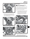
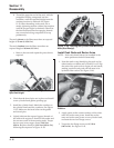
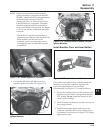
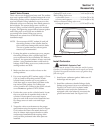
NOTE: If the wires were disconnected from the
ignition modules on engines with SMART-
SPARK
™
, reattach the leads and seal the base
of the terminal connectors with GE/
Novaguard G661 (see Section 2) or Fel-Pro
Lubri-Sel dielectric compound. The beads
should overlap between the terminals* to
form a solid bridge of compound. See Figure
11-50. Do not put any compound inside the
terminals.
*The 24 584 15-S ignition modules have a
separator barrier between the terminals. On
these modules, seal the base of the
terminals, but it is not necessary to have
overlapping beads of sealant between the
connections.
Figure 11-50. Sealant Applied to Terminals.
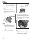
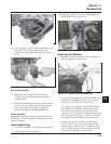
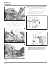
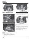
2. Connect the kill lead to the tab terminal on
standard ignition modules. See Figure 11-51.
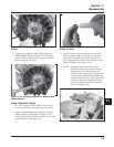
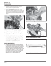
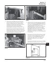
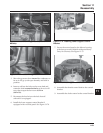
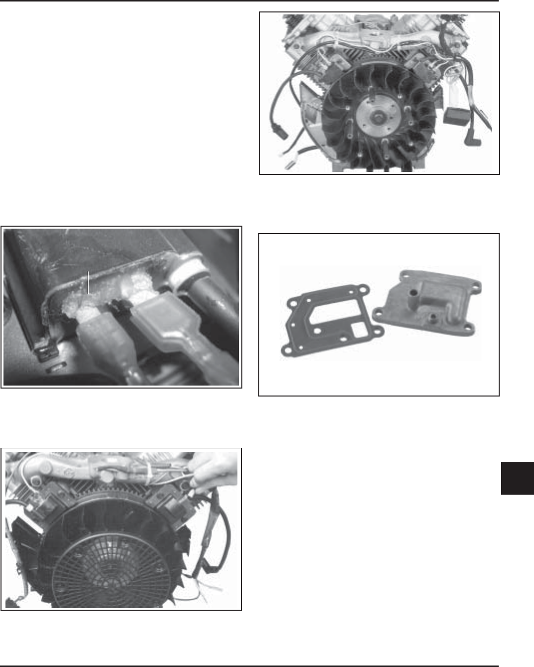
Figure 11-53. Breather Cover and Gasket.
RTV sealant was used on early models between the
breather cover and the crankcase. A gasket with
imprinted sealant beads is now used and
recommended. See Figure 11-53. Install as follows.
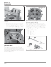
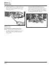
1. Be sure the sealing surfaces of the crankcase and
breather cover are clean of old gasket material or
RTV sealant. Do not scrape the surfaces as this
could result in leakage.
2. Check to make sure there are no nicks or burrs on
the sealing surfaces.
3. Position the breather gasket and cover on the
crankcase. Install the first two hex flange screws
in locations 3 and 4 shown in Figure 11-54. Finger
tighten at this time.
Figure 11-51. Connecting Kill Leads on Standard
Ignition Modules.
Figure 11-52. Connect Leads on SMART-SPARK
™
Ignition Modules.
Install Breather Cover and Inner Baffles
Sealant