


11.9
Section 11
Reassembly
11
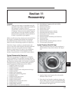
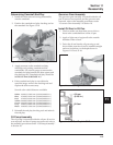
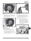
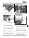
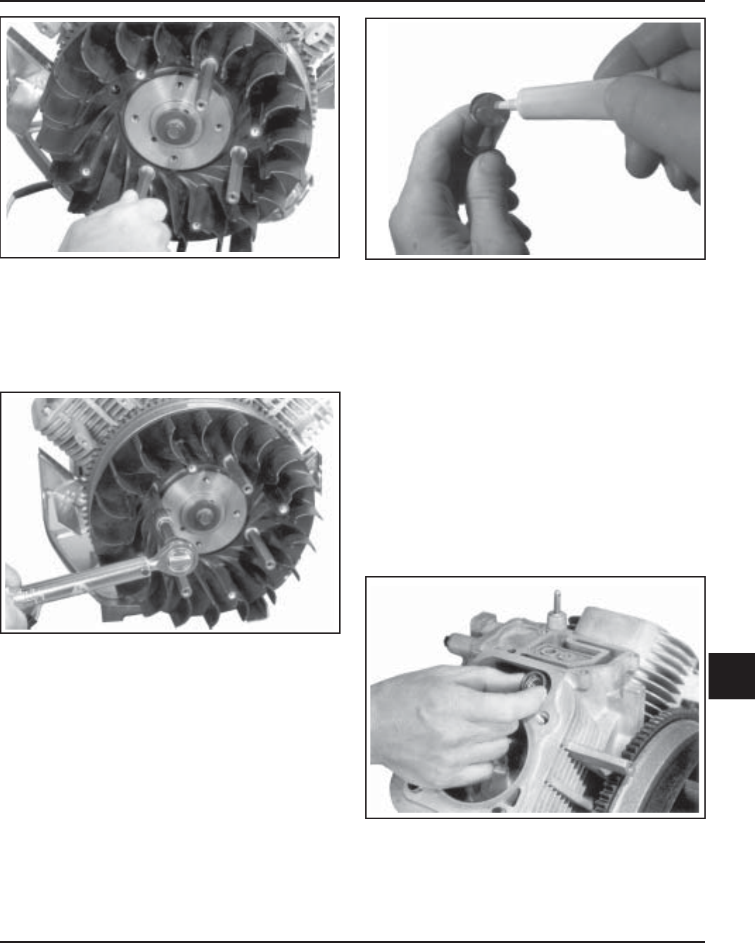
Figure 11-28. Installing Supports for Metal Grass
Screen.
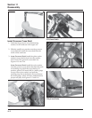
2. Tighten the supports with a torque wrench to
9.9 N·m (99 in. lb.). See Figure 11-29. The grass
screen will be installed to the supports after the
blower housing is in place.
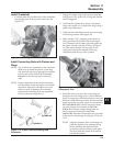
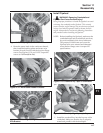
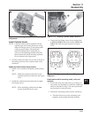
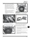
Figure 11-30. Applying Camshaft Lubricant to
Bottom of Lifters.
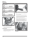
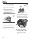
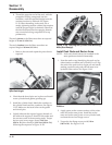
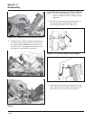
3. Note the mark or tag identifying the hydraulic
lifters as either intake or exhaust and cylinder 1
or cylinder 2. Install the hydraulic lifters into
their appropriate locations in the crankcase. Do
not use a magnet. See Figure 11-31.
NOTE: Hydraulic lifters should always be
installed in the same position as before
disassembly. The exhaust lifters are
located on the output shaft (oil pan) side
of the engine while the intake lifters are
located on the fan side of the engine. The
cylinder numbers are embossed on the
top of the crankcase and each cylinder
head. See Figure 11-32.
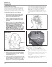
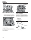
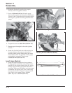
Figure 11-29. Torquing Supports for Metal Screen
(Some Models).
Install Hydraulic Lifters
1. See “Servicing Hydraulic Lifters” in Section 10
for lifter preparation (bleed down) procedures.
2. Apply camshaft lubricant (see Section 2) to the
bottom surface of each lifter. See Figure 11-30.
Lubricate the hydraulic lifters and the lifter bores
in the crankcase with engine oil.
Figure 11-31. Installing Hydraulic Lifters.