


5B.3
Section 5B
EFI Fuel System
5B
Gasoline/Alcohol blends
Gasohol (up to 10% ethyl alcohol, 90% unleaded
gasoline by volume) is approved as a fuel for Kohler
EFI engines. Other gasoline/alcohol blends are not
approved.
Gasoline/Ether blends
Methyl Tertiary Butyl Ether (MTBE) and unleaded
gasoline blends (up to a maximum of 15% MTBE by
volume) are approved as a fuel for Kohler EFI engines.
Other gasoline/ether blends are not approved.
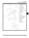
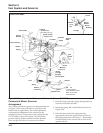
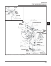
EFI Fuel System Components
General
The Electronic Fuel Injection (EFI) system is a
complete engine fuel and ignition management
design. The system includes the following principal
components:
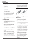
• Fuel Pump
• Fuel Filter
• Fuel Rail
• Fuel Line(s)
• Fuel Pressure Regulator
• Fuel Injectors
• Throttle Body/Intake Manifold
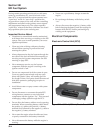
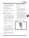
• Engine Control Unit (ECU)
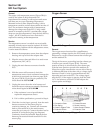
• Ignition Coils
• Engine (Oil) Temperature Sensor
• Throttle Position Sensor (TPS)
• Speed Sensor
• Oxygen Sensor
• Wire Harness Assembly & Affiliated Wiring,
• Malfunction Indicator Light (MIL)
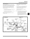
Operation
The EFI system is designed to provide peak engine
performance with optimum fuel efficiency and lowest
possible emissions. The ignition and injection
functions are electronically controlled, monitored and
continually corrected during operation to maintain the
theoretical ideal or “stoichiometric” air/fuel ratio of
14.7:1.
The central component of the system is the Motronic
™
Engine Control Unit (ECU) which manages system
operation, determining the best combination of fuel
mixture and ignition timing for the current operating
conditions.
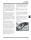
An electric fuel pump is used to move fuel from the
tank through the fuel line and in-line fuel filter. A fuel
pressure regulator maintains a system operating
pressure of 39 psi and returns any excess fuel to the
tank. At the engine, fuel is fed through the fuel rail
and into the injectors, which inject it into the intake
ports. The ECU controls the amount of fuel by varying
the length of time that the injectors are “on.” This can
range from 1.5-8.0 milliseconds depending on fuel
requirements. The controlled injection of the fuel
occurs each crankshaft revolution, or twice for each 4-
stroke cycle. One-half the total amount of fuel needed
for one firing of a cylinder is injected during each
injection. When the intake valve opens, the fuel/air
mixture is drawn into the combustion chamber,
ignited, and burned.
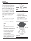
The ECU controls the amount of fuel being injected
and the ignition timing by monitoring the primary
sensor signals for engine temperature, speed (RPM),
and throttle position (load). These primary signals are
compared to preprogrammed “maps” in the ECU
computer chip, and the ECU adjusts the fuel delivery
to match the mapped values. After the engine reached
operating temperature, an exhaust gas oxygen sensor
provides feedback to the ECU based upon the amount
of unused oxygen in the exhaust, indicating whether
the fuel mixture being delivered is rich or lean. Based
upon this feedback, the ECU further adjusts fuel input
to re-establish the ideal air/fuel ratio. This operating
mode is referred to as “closed loop” operation. The
EFI system operates “closed loop” when all three of
the following conditions are met:
a. The oil temperature is greater than 35°C (86°F).
b. The oxygen sensor has warmed sufficiently to
provide a signal (minimum 375°C, 709°F).
c. Engine operation is at a steady state (not starting,
warming up, accelerating, etc.).
During “closed loop” operation the ECU has the
ability to readjust temporary and learned adaptive
controls, providing compensation for changes in
overall engine condition and operating environment,
so it will be able to maintain the ideal air/fuel ratio of
14.7:1. The system requires a minimum engine oil
temperature greater than 55°C (130°F) to properly
adapt. These adaptive values are maintained as long
as the ECU is “powered up” by the battery.