


5B.7
Section 5B
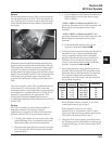
EFI Fuel System
5B
General
The throttle position sensor (TPS) is used to indicate
throttle plate angle to the ECU. Since the throttle (by
way of the governor) reacts to engine load, the angle
of the throttle plate is directly related to the load on
the engine.
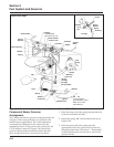
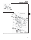
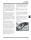
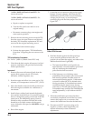
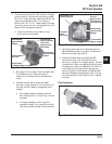
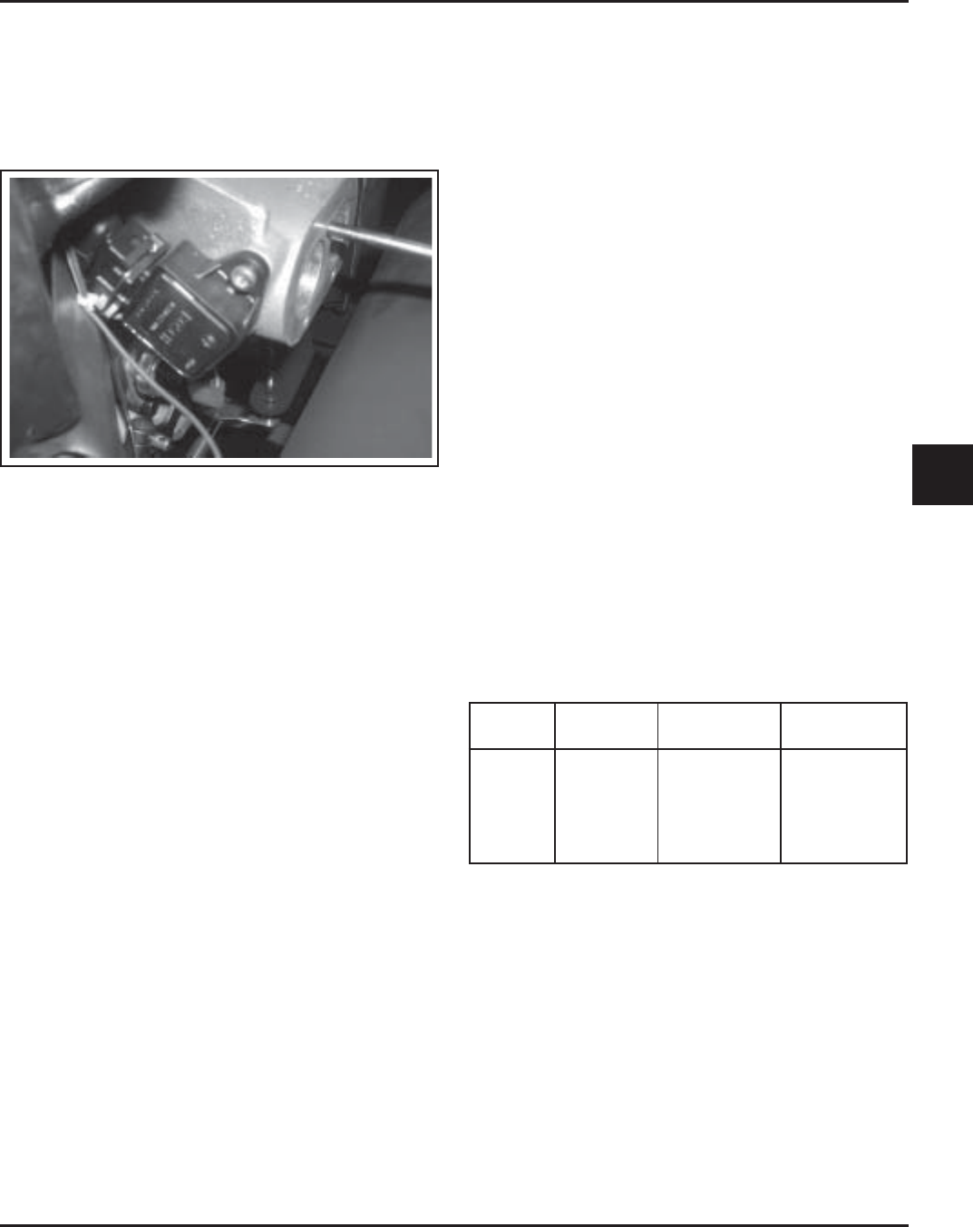
Figure 5B-6. TPS Location.
Mounted on the throttle body/intake manifold and
operated directly off the end of the throttle shaft, the
TPS works like a rheostat, varying the voltage signal
to the ECU in direct correlation to the angle of the
throttle plate. This signal, along with the other sensor
signals, is processed by the ECU and compared to the
internal pre-programmed maps to determine the
required fuel and ignition settings for the amount of
load.
The correct position of the TPS is established and set
at the factory. Do not loosen the TPS or alter the
mounting position unless absolutely required by fault
code diagnosis or throttle shaft service. If the TPS is
loosened or repositioned, the appropriate “TPS
Initialization Procedure must be performed to
reestablish the baseline relationship between the ECU
and the TPS.
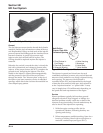
Service
The TPS is a sealed, non-serviceable assembly. If
diagnosis indicates a bad sensor, complete
replacement is necessary. If a blink code indicates a
problem with the TPS, it can be tested as follows:
1. Counting the number of turns, back out the idle
speed adjusting screw (counterclockwise) until
the throttle plates can be closed completely.
2. Disconnect the main harness connector from the
ECU, but leave the TPS mounted to the throttle
body/manifold.
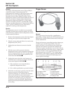
3. a. Use an ohmmeter and connect the ohmmeter
leads as follows to test: (See chart on page
5B.26 or 5B.29.).
“24 Pin” (MSE 1.0) Plastic-Cased ECU: Red
(positive) ohmmeter lead to #8 pin terminal, and
Black (negative) ohmmeter lead to #4 pin
terminal.
“32 Pin” (MSE 1.1) Plastic-Cased ECU: Red
(positive) ohmmeter lead to #8 pin terminal, and
Black (negative) ohmmeter lead to #4 pin
terminal.
b. Hold the throttle closed and check the
resistance. It should be 800-1200
ΩΩ
ΩΩ
Ω.
4. Leave the leads connected to the pin terminals as
described in step 3. Rotate the throttle shaft
slowly counterclockwise to the full throttle
position. Monitor the dial during rotation for
indication of any momentary short or open
circuits. Note the resistance at the full throttle
position. It should be 1800-3000
ΩΩ
ΩΩ
Ω.
5. Disconnect the main wiring harness connector
from the TPS, leaving the TPS assembled to the
manifold. Refer to the chart below and perform
the resistance checks indicated between the
terminals in the TPS switch, with the throttle in
the positions specified.
If the resistance values in steps 3, 4, and 5 are
within specifications, go to step 6.
If the resistance values are not within
specifications, or a momentary short or open
circuit was detected during rotation (step 4), the
TPS needs to be replaced, go to step 7.
6. Check the TPS circuits (input, ground) between
the TPS plug and the main harness connector for
continuity, damage, etc. See chart on page 5B-26
or 5B-29.
Throttle
Position
Closed
Closed
Full
Full
Any
Between
Terminals
2 & 3
1 & 3
2 & 3
1 & 3
1 & 2
Resistance
Value (Ω)
800-1200
1800-3000
1800-3000
800-1200
1600-2500
Continuity
Yes
Yes
Yes
Yes
Yes