


5B.8
Section 5B
EFI Fuel System
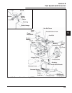
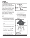
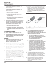
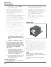
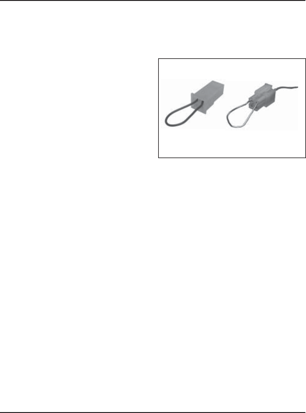
Figure 5B-7. Service Connector Plug, Plastic
Cased ECU Harness.
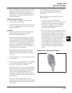
8. Hold the throttle against the idle speed stop
screw, turn the ignition switch to the “on”
position (do not start the engine), and observe the
Malfunction Indicator Light (MIL).
a. The light should blink on/off quickly for
approximately 3 seconds and then go off and
stay off, indicating the initialization
procedure has been successful.
b. If the light stays on or blinking ceases
prematurely, the procedure was unsuccessful
and must be repeated. Possible causes for
unsuccessful learning may be: 1) Movement
occurred in either the TPS or throttle shaft
during procedure, 2) Crankshaft movement
wasdetected by the speed sensor during
procedure, 3) Throttle plate position was out
of learnable range (recheck the 1500 RPM idle
speed adjustment), or 4) Problem with ECU
or TPS.
9. When the initialization procedure has been
successfully completed, turn off the key switch,
remove the jumper wire or connector, and
remove the rubber band from the throttle lever.
10. Disconnect the ECU connector plug or the
negative (-) battery cable temporarily (one
minute minimum) to clear all learned
adjustments.
“24 Pin” (MSE 1.0) Plastic-Cased ECU: Pin
circuits #8 and #4.
“32 Pin” (MSE 1.1) Plastic-Cased ECU: Pin
circuits #8 and #4.
a. Repair or replace as required.
b. Turn the idle speed screw back in to its
original setting.
c. Reconnect connector plugs, start engine and
retest system operation.
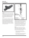
7. Remove the two mounting screws from the TPS.
Save the screws for reuse. Remove and discard
the faulty TPS. Install the replacement TPS and
secure with the original mounting screws.
a. Reconnect both connector plugs.
b. Perform the appropriate “TPS Initialization
Procedure” integrating the new sensor to the
ECU.
TPS Initialization Procedure
For “24 Pin” (MSE 1.0) Plastic-Cased ECU only
1. Check that the basic engine, all sensors, fuel, fuel
pressure, and battery are good and functionally
within specifications.
Important!
2. Remove/disconnect all external loads from the
engine (belts, pumps, electric PTO clutch,
alternator, rectifier-regulator, etc.).
3. Start the engine and allow it to warm up for 5-10
minutes, so oil temperature is above 55°C (130°F).
4. Move the throttle control to the idle position and
allow the engine to stabilize for a minimum of
one minute.
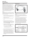
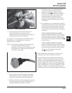
5. Install a heavy rubber band around the throttle
lever and the manifold boss. On some EFI engines
there is a dampening spring on the end of the idle
speed screw. The dampening spring (if used)
should be fully compressed and the tab on the
throttle lever in direct contact with the speed
screw. Adjust the idle speed to 1500 RPM, using a
tachometer.
6. Shut off the engine.
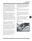
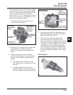
7. Locate the service connector plug in the wiring
harness. Connect a jumper wire from the TPS
initialization pin #24 (violet wire) to the battery
voltage pin (red wire), or use the jumper
connector plug with the blue jumper wire. See
Figure 5B-7.