


11.19
Section 11
Reassembly
11
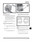
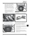
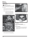
Install Valve Covers
Three valve cover designs have been used. The earliest
type used a gasket and RTV sealant between the cover
and sealing surface of the cylinder head. The second
type had a black O-Ring installed in a groove on the
underside of the cover and may have metal spacers in
the bolt holes. The newest design uses a yellow or
brown O-Ring, and the bolt hole spacers are molded
in place. The tightening torque differs between gasket
and O-Ring style covers. Kits are available for
converting to the latest O-Ring type covers.
Differences are pointed out in the following
installation steps.
NOTE: Do not scrape old RTV sealant (if used) off
the sealing surface of the cylinder head as
this could cause damage and result in leaks.
The use of gasket remover solvent (paint
remover) is recommended.
1. If using the gasket or sealant type cover, prepare
the sealing surfaces of the cylinder head and
cover as directed in Service Bulletin 252. Refer to
Section 2, for approved sealants. Always use fresh
sealant – using outdated sealant could result in
leakage. With O-Ring type covers, make sure the
sealing surfaces are clean.
2. Make sure there are no nicks or burrs on the
sealing surfaces.
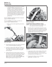
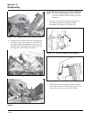
3. For covers requiring RTV sealant, apply a 1.5 mm
(1/16 in.) bead to the sealing surface of both
cylinder heads, install a new cover gasket on
each, then apply a second bead of sealant on the
top surface of the gaskets. For O-Ring type
covers, install a new O-Ring in the groove of each
cover. Do not use gaskets or RTV sealant.
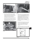
4. Position the covers on the cylinder heads. Locate
the cover with the oil separator hole on the #1
cylinder. If loose spacers were used, insert a
spacer in each of the screw holes. Install the four
hex flange screws in each cover and finger
tighten.
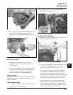
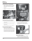
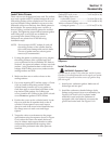
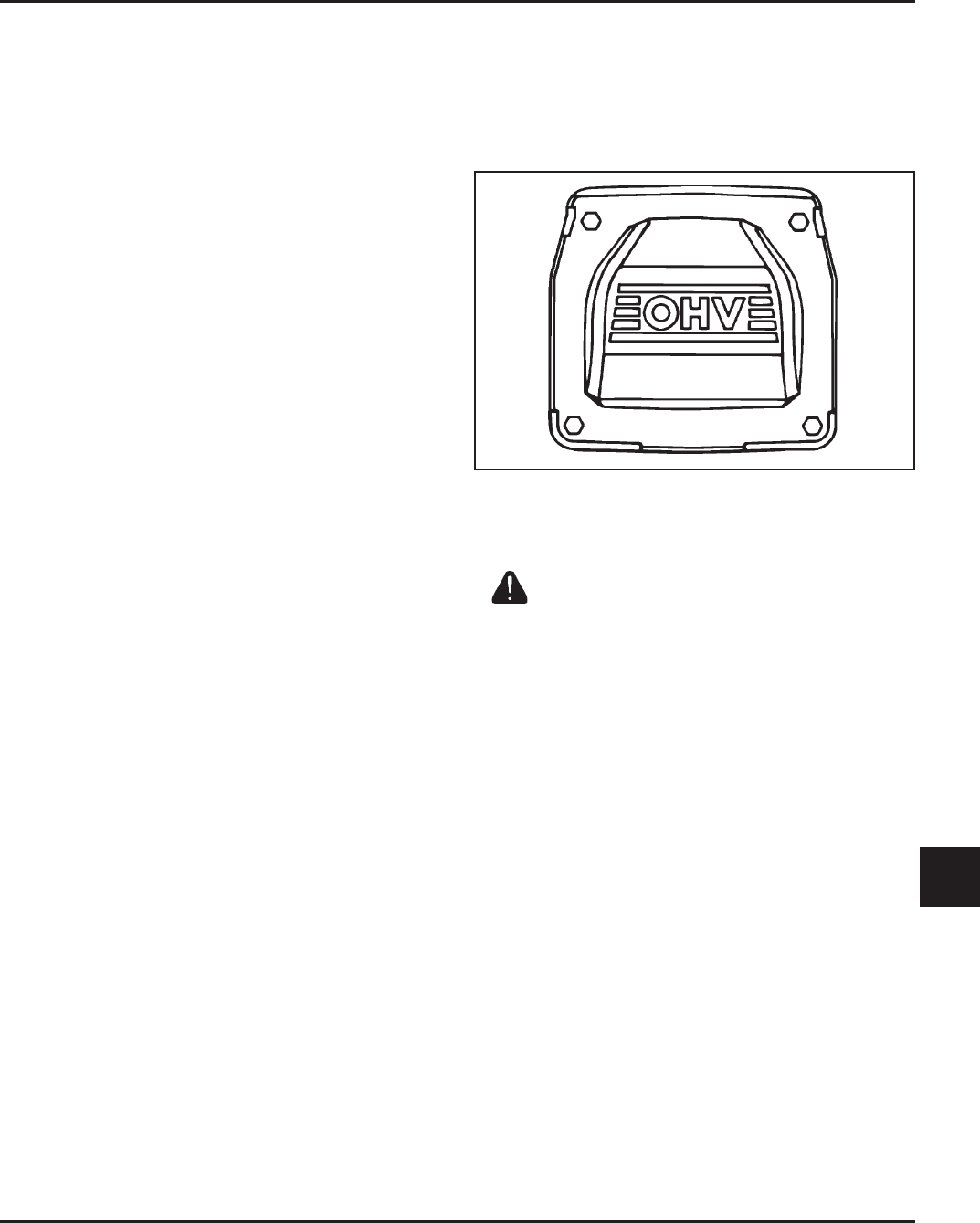
5. Torque the valve cover fasteners to the proper
specification using the sequence shown in Figure
11-66, unless the screws also attach the heavy-
duty air cleaner main support bracket or other
components. Installation and torquing of the
screws will be performed after these parts are
installed.
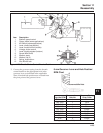
Figure 11-66. Valve Cover Fastener Torque
Sequence.
Install Carburetor
WARNING: Explosive Fuel!
Gasoline may be present in the carburetor and fuel system.
Gasoline is extremely flammable and its vapors can explode
if ignited. Keep sparks and other sources of ignition away
from the engine.
1. Install a new carburetor gasket. Make sure all
holes align and are open.
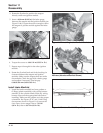
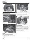
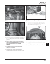
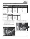
2. Install the carburetor, throttle linkage, choke
linkage, and governor lever as an assembly. See
Figures 11-67 and 11-68. If a plastic intake
manifold is used and/or the carburetor is
equipped with a fuel solenoid, reconnect the
ground and main leads. See Figure 11-69.
1
2
3
4
Gasket/RTV style cover..................... 3.4 N·m (30 in. lb.)
Black O-Ring style cover
w/shoulder screws ........................ 5.6 N·m (50 in. lb.)
w/screws and spacers ................... 9.9 N·m (88 in. lb.)
Yellow or Brown O-Ring style cover
w/integral spacers ......................... 6.2 N·m (55 in. lb.)