


5B.5
Section 5B
EFI Fuel System
5B
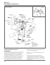
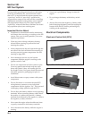
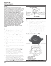
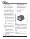
Two different ECU styles have been used in CV EFI
production. Each has a plastic case, but they differ in
having a 24 pin or 32 pin connector block, and are
identified as MSE 1.0 or MSE 1.1 respectively. See
Figures 5B-1 and 5B-2. Basic function and operating
control remains the same between the two, however
due to differences in the internal circuitry as well as
the wiring harness, the ECU’s are not interchangeable.
Certain service/troubleshooting procedures will also
differ, so where applicable, they are covered
individually as: “24 Pin” (MSE 1.0) Plastic-Cased
ECU, or “32 Pin” (MSE 1.1) Plastic-Cased ECU.
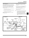
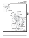
General
The ECU is the brain or central processing computer
of the entire EFI system. During operation, sensors
continuously gather data which is relayed through the
wiring harness to input circuits within the ECU.
Signals to the ECU include: ignition (on/off),
crankshaft position and speed (RPM), throttle
position, oil temperature, exhaust oxygen levels, and
battery voltage. The ECU compares the input signals
to the programmed maps in its memory to determine
the appropriate fuel and spark requirements for the
immediate operating conditions. The ECU then sends
output signals to set the injector duration and ignition
timing.
The ECU continually performs a diagnostic check of
itself, each of the sensors, and the system
performance. If a fault is detected, the ECU turns on
the Malfunction Indicator Light (MIL) on the
equipment control panel, stores the fault code in its
fault memory, and goes into a default operating mode.
Depending on the significance or severity of the fault,
normal operation may continue, or “limp home”
operation (slowed speed, richer running) may be
initiated. A technician can access the stored fault code
using a “blink code” diagnosis flashed out through the
MIL. An optional computer software diagnostic
program is also available, see Section 2.
The ECU requires a minimum of 7.0 volts to operate.
The adaptive memory in the ECU is operational
whenever the required voltage is present, however the
adapted values are lost if the power supply is
disrupted for any reason. The ECU will “relearn” the
adapted values if the engine is operated for 10-15
minutes at varying speeds and loads after the oil
temperature exceeds 55°C (130°F).
To prevent engine over-speed and possible failure, a
“rev-limiting” feature is programmed into the ECU. If
the maximum RPM limit (4500) is exceeded, the ECU
suppresses the injection signals, cutting off the fuel
flow. This process repeats itself in rapid succession,
limiting operation to the preset maximum.
Service
Never attempt to disassemble the ECU. It is sealed to
prevent damage to internal components. Warranty is
void if the case is opened or tampered with in any
way.
All operating and control functions within the ECU
are preset. No internal servicing or readjustment may
be performed. If a problem is encountered, and you
determine the ECU to be faulty, contact your source of
supply. Do not replace the ECU without factory
authorization.
The relationship between the ECU and the throttle
position sensor (TPS) is very critical to proper system
operation. If the TPS or ECU is changed, or the
mounting position of the TPS is altered, the
appropriate “TPS Initialization Procedure” (see pages
5B.8 and 5B.9) must be performed to restore the
synchronization.
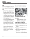
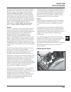
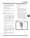
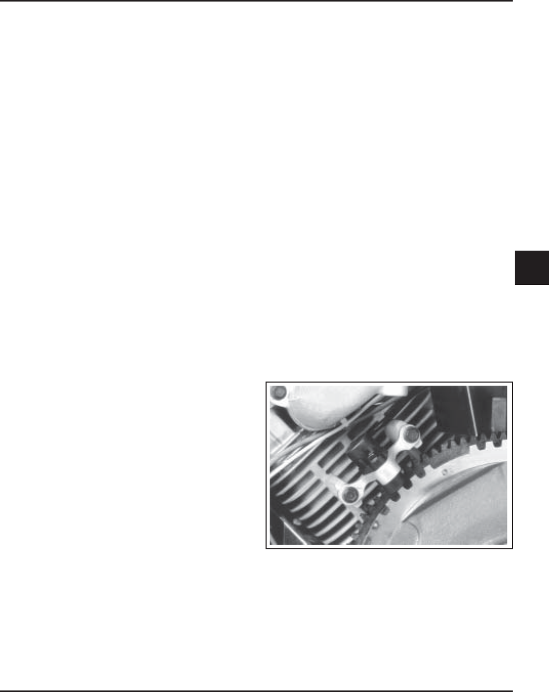
Engine Speed Sensor
Figure 5B-3. Engine Speed Sensor.