


8.7
8
Section 8
Electrical System and Components
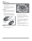
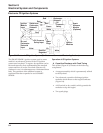
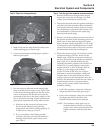
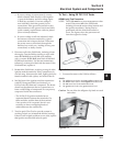
Operation: The ignition module for this system
operates in the same fashion as the fixed timing
module, except the trigger circuit for the
semiconductor (L2, Figure 8-5) is replaced by the
spark advance module (Figure 8-7).
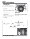
The pulse generated by the input coil of the ignition
module (L1, Figure 8-5) is fed to the input of the
conditioning circuit. The conditioning circuit shapes
this pulse, putting it in a useable form for the
additional circuits. This pulse starts the charge pump,
which charges a capacitor in a linear fashion that can
be directly related to the engine speed. At the same
time the pulse resets the delay circuit for length of the
pulse width. The comparator is off during this period
and no output is generated. As soon as the original
pulse drops back to zero, the capacitor in the delay
circuit begins to charge.
When the charge on the delay capacitor exceeds the
charge on the charge pump capacitor the comparator
changes state, activating the pulse generator. This
pulse turns “ON” the CD ignition module
semiconductor. Energy is then transferred to the
secondary of the output transformer (T1, Figure 8-5).
The high voltage pulse generated here is delivered to
the spark plug, causing arcing of the spark gap and
igniting the fuel-air mixture in the combustion
chamber. As the trigger pulse is generated, all
associated circuits are reset, their capacitors
discharged. The longer it takes the delay circuit to
surpass the charge pump capacitor voltage, the later
the trigger pulse will occur, retarding the timing
accordingly.
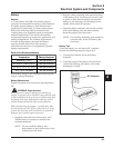
Troubleshooting CD Ignition Systems
The CD ignition systems are designed to be trouble
free for the life of the engine. Other than periodically
checking/replacing the spark plugs, no maintenance or
timing adjustments are necessary or possible.
Mechanical systems do occasionally fail or break
down however, so the following troubleshooting
information is provided to help you get to the root of
a reported problem.
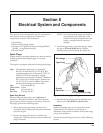
CAUTION: High-Energy Electric Spark!
The CD ignition systems produce a high-energy electric
spark, but the spark must be discharged, or damage to the
system can result. Do not crank or run an engine with a
spark plug lead disconnected. Always provide a path for the
spark to discharge to ground.
Reported ignition problems are most often due to
poor connections. Before beginning the test procedure,
check all external wiring. Be certain all ignition-
related wires are connected, including the spark plug
leads. Be certain all terminal connections fit snugly.
Make sure the ignition switch is in the run position.
NOTE: The CD ignition systems are sensitive to
excessive load on the kill lead. If a customer
complains of hard starting, low power, or
misfire under load, it may be due to excessive
draw on the kill circuit. Perform the
appropriate test procedure.
Test Procedure for Standard (Fixed Timing) CD
Ignition System
Isolate and verify the trouble is within the engine
ignition system.
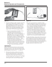
1. Locate the plug connectors where the wiring
harnesses from the engine and equipment are
joined. Separate the connectors and remove the
white “kill” lead from the engine connector.
Rejoin the connectors and position or insulate the
kill lead terminal so it cannot touch ground. Try
to start** the engine to verify whether the
reported problem is still present.
a. If the problem is gone, the electrical
system on the unit is suspect. Check the key
switch, wires, connections, safety interlocks,
etc.
b. If the problem persists the condition is
associated with the ignition or electrical
system of the engine. Leave the kill lead
isolated until all testing is completed.
**NOTE: If the engine starts or runs during any of the
testing, you may need to ground the kill lead
to shut it down. Because you have
interrupted the kill circuit, it may not stop
using the switch.
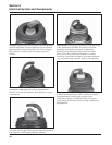
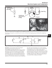
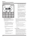
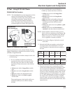
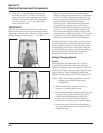
2. Test for spark on both cylinders with Kohler
ignition tester (see Section 2). Disconnect one
spark plug lead and connect it to the post
terminal of the tester. Connect the clip to a good
ground, not to the spark plug. Crank the engine
and observe the tester spark gap. Repeat the
procedure on the other cylinder. Remember to
reconnect the first spark plug lead.