


9.10
Section 9
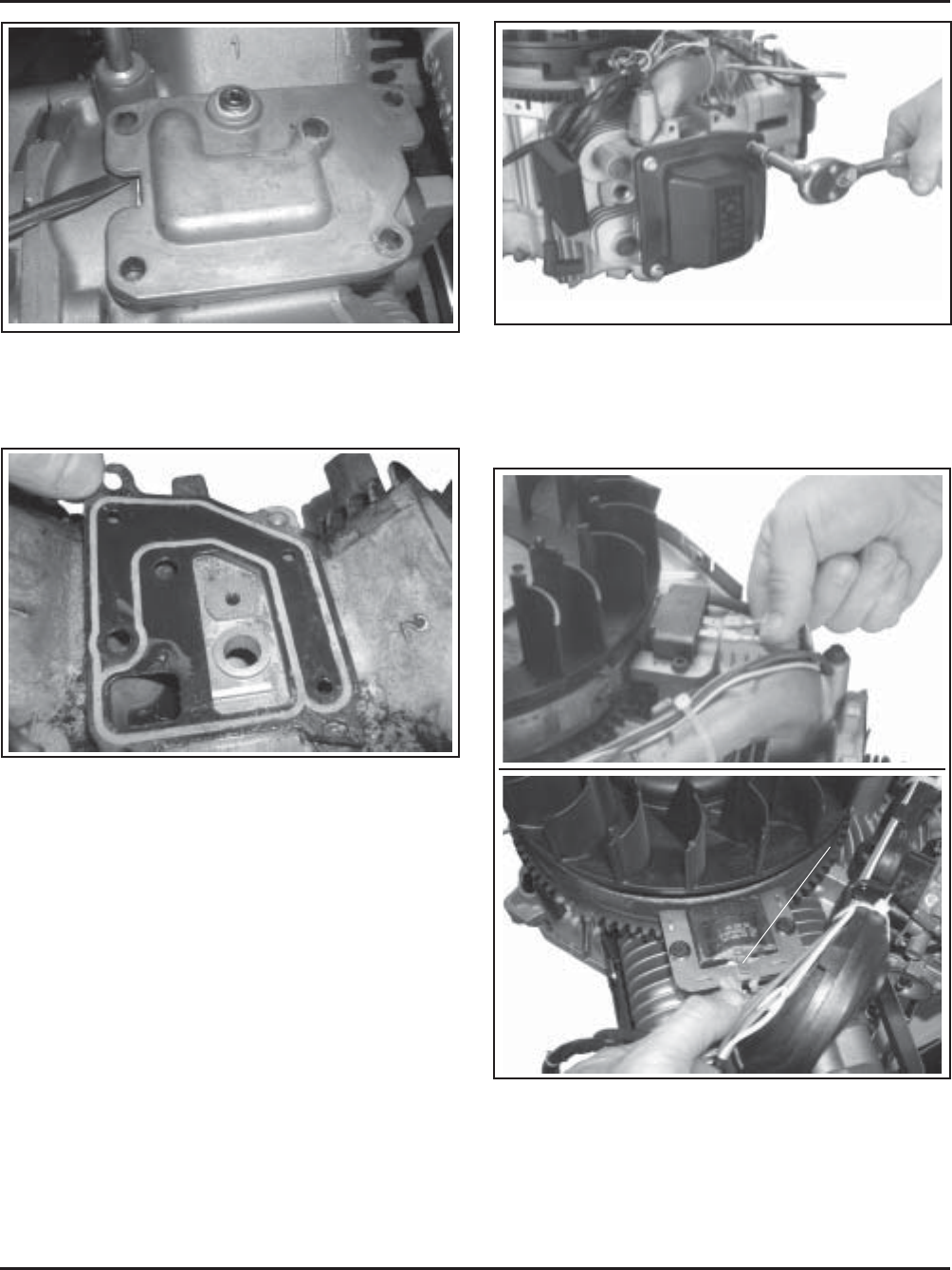
Disassembly
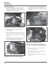
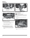
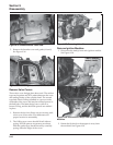
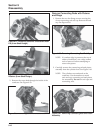
Figure 9-37. Removing Valve Cover.
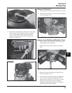
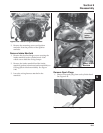
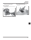
Remove Ignition Modules
1. Disconnect the lead(s) from each ignition module.
See Figure 9-38.
Figure 9-38. Disconnect Lead(s) from Ignition
Modules.
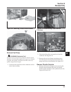
2. Rotate the flywheel so the magnet is away from
the modules. See Figure 9-39.
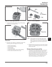
SMART-SPARK
™
Module Leads
Fixed Timing
Ignition Module
Kill Lead
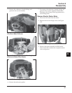
Figure 9-36. Removing Breather Cover Gasket.
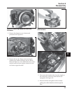
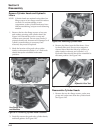
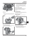
Remove Valve Covers
Three valve cover designs have been used. The earliest
type used a gasket and RTV sealant between the cover
and sealing surface of the cylinder head. The second
type had a black O-Ring installed in a groove on the
underside of the cover and may have metal spacers in
the bolt holes. The latest design uses a yellow or
brown O-Ring, and the bolt hole spacers are molded
in place.
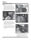
1. Remove the four hex flange screws securing each
valve cover. Note valve cover differences for
proper location in reassembly.
2. The O-Ring type covers should lift off without
prying. If loose spacers are present, save them.
With the gasket type, break the seal by carefully
prying under the edges of the cover.
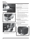
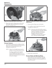
Figure 9-35. Break Breather Cover Seal.
5. Remove the breather cover and gasket (if used).
See Figure 9-36.