


11.3
Section 11
Reassembly
11
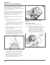
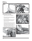
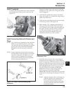
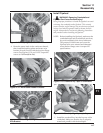
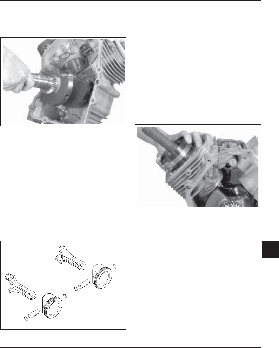
Figure 11-7. Installing Crankshaft.
Install Connecting Rods with Pistons and
Rings
NOTE: The cylinders are numbered on the crankcase.
Make sure to install the piston, connecting
rod, and end cap into its appropriate cylinder
bore as previously marked at disassembly.
Do not mix the end caps and connecting
rods.
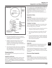
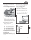
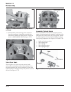
NOTE: Proper orientation of the piston/connecting
rod assemblies inside the engine is extremely
important. Improper orientation can cause
extensive wear or damage. Be certain the
pistons and connecting rods are assembled
exactly as shown in Figure 11-8.
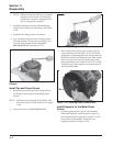
1. Stagger the piston rings in the grooves until the
end gaps are 120° apart. The oil ring rails should
also be staggered.
2. Lubricate the cylinder bore, piston, and piston
rings with engine oil. Compress the rings using a
piston ring compressor.
3. Lubricate the crankshaft journals and connecting
rod bearing surfaces with engine oil.
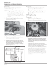
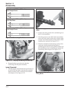
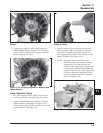
4. Make sure the ‘‘Fly’’ stamping on the piston is
facing towards the flywheel side of the engine.
Use a hammer with a rubber grip and gently tap
the piston into the cylinder as shown in Figure
11-9. Be careful that the oil ring rails do not
spring free between the bottom of the ring
compressor and the top of the cylinder.
Install Crankshaft
1. Carefully slide the flywheel end of the crankshaft
through the main bearing in the crankcase. See
Figure 11-7.
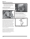
Figure 11-8. Proper Piston Connecting Rod
Orientation.
Cylinder #1
Cylinder #2
Figure 11-9. Installing Piston Assembly Using Ring
Compressor Tool.
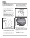
5. Install the inner rod cap to the connecting rod
using the two hex flange screws. Three different
types of connecting rod bolts have been used, and
each has a different torque value. If 8 mm straight
shank type bolts are used, torque in increments to
22.7 N·m (200 in. lb.). If 8 mm step-down bolts
are used, torque in increments to 14.7 N·m
(130 in. lb.). If 6 mm straight shank bolts are
used, torque in increments to 11.3 N·m
(100 in. lb.). Illustrated instructions are provided
in the service rod package. See Figures 11-10 and
11-11.
NOTE: Align the chamfer of the connecting rod
with the chamfer of its mating end cap.
When installed, the flat faces of the
connecting rods should face each other.
The faces with the raised rib should be
toward the outside.