


5B.14
Section 5B
EFI Fuel System
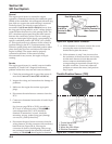
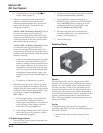
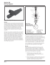
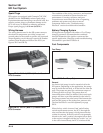
1. Filter Strainer In
Fuel Supply
2. Electrical Connection
3. Solenoid Winding
Multi-Orifice
Director Plate With
Calibrated Opening
4. Valve Housing
5. Armature
6. Valve Body
7. Valve Needle
1
2
3
4
5
6
7
Figure 5B-15. Style 2 Fuel Injector.
General
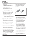
The fuel injectors mount into the throttle body/intake
manifold, and the fuel rail attaches to them at the top
end. Replaceable O-Rings on both ends of the injector
prevent external fuel leakage and also insulate it from
heat and vibration. A special clip connects each
injector to the fuel rail and holds it in place. The
O-Rings should be replaced anytime the injector is
removed.
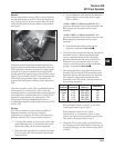
When the key switch is on and the relay is closed, the
fuel rail is pressurized, and voltage is present at the
injector. At the proper instant, the ECU completes the
ground circuit, energizing the injector. The valve
needle in the injector is opened electromagnetically,
and the pressure in the fuel rail forces fuel down
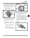
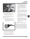
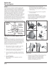
through the inside. The “director plate” at the tip of
the injector (see inset) contains a series of calibrated
openings which directs the fuel into the manifold in a
cone-shaped spray pattern.
Figure 5B-16. Fuel Injector Details.
The injector is opened and closed once for each
crankshaft revolution, however only one-half the total
amount of fuel needed for one firing is injected during
each opening. The amount of fuel injected is
controlled by the ECU and determined by the length
of time the valve needle is held open, also referred to
as the “injection duration” or “pulse width”. It may
vary in length from 1.5-8 milliseconds depending on
the speed and load requirements of the engine.
Service
Injector problems typically fall into three general
categories: electrical, dirty/clogged, or leakage. An
electrical problem usually causes one or both of the
injectors to stop functioning. Several methods may be
used to check if the injectors are operating.
1. With the engine running at idle, feel for
operational vibration, indicating that they are
opening and closing.
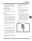
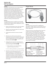
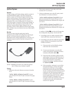
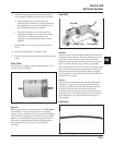
2. When temperatures prohibit touching, listen for a
buzzing or clicking sound with a screwdriver or
mechanic’s stethoscope (see Figure 5B-17).