


8.26
Section 8
Electrical System and Components
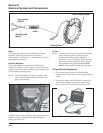
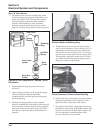
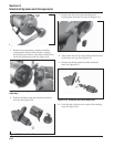
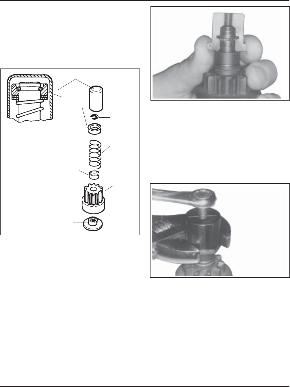
Figure 8-36. Assembling Inner Half of Tool Around
Armature Shaft and Retaining Ring.
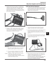
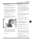
5. Thread the center screw into the removal tool
until you feel resistance. Use a wrench (1-1/8" or
adjustable) to hold the base of the removal tool.
Use another wrench or socket (1/2" or 13 mm) to
turn the center screw clockwise (see Figure 8-37).
The resistance against the center screw will tell
you when the retaining ring has popped out of
the groove in the armature shaft.
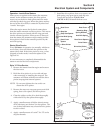
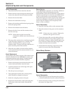
Style ‘‘B’’ Drive Service
1. The rubber dust cover has a molded lip on the
inside that snaps into a groove in the dust cover
spacer (see Figure 8-35). Turn the drive pinion
clockwise until it reaches the fully extended
position. While holding it in the extended
position, grasp the tip of the dust cover with a
pliers or vise grip and pull it free from the spacer.
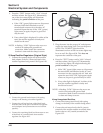
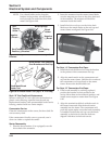
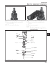
Dust Cover
Retaining
Ring
Anti-Drift
Spring
Drive
Pinion
Drive Nut
(Collar)
Dust Cover
Spacer
Spring
Retainer
Figure 8-35. Drive Components, ‘‘Bonded’’ Inertia
Drive Starter.
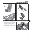
2. Disassemble the snap ring removal tool (see
Section 2).
3. Again referring to Figure 8-35, grasp the spring
retainer and push it toward the starter,
compressing the anti-drift spring and exposing
the retaining ring.
4. Holding the spring retainer in the retracted
position, assemble the inner halves of the removal
tool around the armature shaft with the retaining
ring in the inner groove (see Figure 8-36). Slide
the collar over the inner halves to hold them in
position.
Figure 8-37. Holding Tool and Turning Center
Screw (Clockwise) to Remove Retaining Ring.
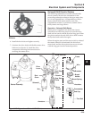
6. Remove the drive components from the armature
shaft, paying attention to the sequence. If the
splines are dirty, clean them with solvent.
7. The splines should have a light film of lubricant.
Relubricate as necessary with Kohler starter drive
lubricant (see Section 2). Reinstall or replace the
drive components, assembling them in the
reverse order they were removed.