


190-00595-01 Rev. B
Garmin G1000 Pilot’s Guide for the Beechcraft A36/G36
79
ENGINE INDICATION SYSTEM
SYSTEM
OVERVIEW
FLIGHT
INSTRUMENTS
EIS
AUDIO PANEL
& CNS
FLIGHT
MANAGEMENT
HAZARD
AVOIDANCE
AFCS
ADDITIONAL
FEATURES
APPENDICES INDEX
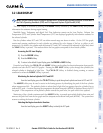
SECTION 3 ENGINE INDICATION SYSTEM
NOTE: Refer to the Pilot’s Operating Handbook (POH) and FAA Approved Airplane Flight Manual (AFM) for
operating limitations.
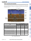
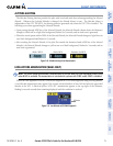
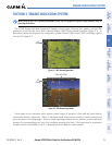
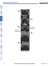
The G1000 Engine Indication System (EIS) displays critical engine, electrical, fuel quantity and fuel flow
parameters on the left side of the Multi Function Display (MFD) during normal operations (Figure 3-1). In
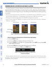
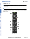
Reversionary Mode, the displays are re-configured to present Primary Flight Display (PFD) symbology together
with the EIS (Figure 3-2).
EIS
Display
Figure 3-1 MFD (Normal Operations)
Figure 3-2 PFD (Reversionary Mode)
EIS
Display
Failed NAV/COM
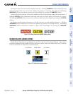
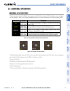
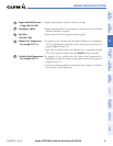
Green bands on the instrument scales indicate normal ranges of operation; yellow and red bands indicate
caution and warning, respectively. White or uncolored bands indicate areas outside of normal operation not
yet in the caution or warning ranges. When an unsafe operating condition occurs, readouts, pointers and labels
change color corresponding to the level of the condition; warnings also flash. If the sensor data for a parameter
becomes invalid or unavailable, a red “X” is displayed across the indicator and/or readout.