


Garmin G1000 Pilot’s Guide for the Beechcraft A36/G36
190-00595-01 Rev. B132
FLIGHT MANAGEMENT
SYSTEM
OVERVIEW
FLIGHT
INSTRUMENTS
EIS
AUDIO PANEL
& CNS
FLIGHT
MANAGEMENT
HAZARD
AVOIDANCE
AFCS
ADDITIONAL
FEATURES
APPENDICESINDEX
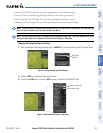
4) Turn the small FMS Knob to display and scroll through the data options list.
5) Select the desired data.
6) Press the ENT Key. Pressing the DFLTS Softkey returns any field to its default setting.
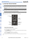
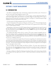
5.2 USING MAP DISPLAYS
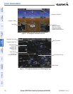
Map displays are used extensively in the G1000 to provide situational awareness in flight. Most G1000 maps
can display the following information:
• Airports, NAVAIDs, airspaces, airways, land data
(highways, cities, lakes, rivers, borders, etc.) with
names
• Map Pointer information (distance and bearing to
pointer, location of pointer, name, and other pertinent
information)
• Map range
• Wind direction and speed
• Map orientation
• Icons for enabled map features
• Aircraft icon (representing present position)
• Nav range ring
• Flight plan legs
• User waypoints
• Track vector
• Topography scale
• Topography data
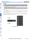
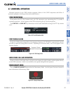
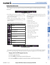
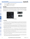
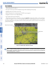
MAP ORIENTATION
Maps are shown in one of four different orientation options, allowing flexibility in determining aircraft
position relative to other items on the map (north up) or for determining where map items are relative to where
the aircraft is going (track up, desired track up, or heading up). The map orientation is shown in the upper
right corner of the map.
Figure 5-3 Map Orientation
• All Map Group Pages (MAP)
• All Waypoint Group Pages (WPT)
• AUX - Trip Planning
• All Nearest Group Pages (NRST)
• Flight Plan Pages (FPL)
• Direct-to Window
• PFD Inset Map
• Procedure Loading Pages
The information in this section applies to the following maps unless otherwise noted: