


190-00595-01 Rev. B
Garmin G1000 Pilot’s Guide for the Beechcraft A36/G36
53
FLIGHT INSTRUMENTS
SYSTEM
OVERVIEW
FLIGHT
INSTRUMENTS
EIS
AUDIO PANEL
& CNS
FLIGHT
MANAGEMENT
HAZARD
AVOIDANCE
AFCS
ADDITIONAL
FEATURES
APPENDICES INDEX
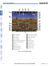
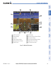
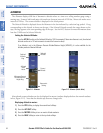
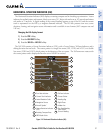
ATTITUDE INDICATOR
Attitude information is displayed over a virtual blue sky and brown ground with a white horizon line. The
Attitude Indicator displays the pitch (indicated by the yellow symbolic aircraft on the pitch scale), roll, and
slip/skid information.
1
Roll Pointer
2
Roll Scale
3
Horizon Line
4
Aircraft Symbol
5
Land Representation
6
Pitch Scale
7
Slip/Skid Indicator
8
Sky Representation
9
Roll Scale Zero
Figure 2-9 Attitude Indicator
5
6
8
7
2
4
3
9
1
The horizon line is part of the pitch scale. Above and below the horizon line, major pitch marks and numeric
labels are shown for every 10˚, up to 80˚. Minor pitch marks are shown for intervening 5˚ increments, up to
25˚ below and 45˚ above the horizon line. Between 20˚ below to 20˚ above the horizon line, minor pitch marks
occur every 2.5˚.
The inverted white triangle indicates zero on the roll scale. Major tick marks at 30˚ and 60˚ and minor tick
marks at 10˚, 20˚, and 45˚ are shown to the left and right of the zero. Angle of bank is indicated by the position
of the pointer on the roll scale.
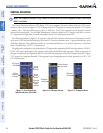
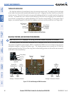
The Slip/Skid Indicator is the bar beneath the roll pointer. The indicator moves with the roll pointer and
moves laterally away from the pointer to indicate lateral acceleration. Slip/skid is indicated by the location of
the bar relative to the pointer. One bar displacement is equal to one ball displacement on a traditional Slip/Skid
Indicator.
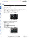
Figure 2-10 Slip/Skid Indication