


190-00595-01 Rev. B
Garmin G1000 Pilot’s Guide for the Beechcraft A36/G36
13
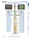
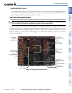
SYSTEM OVERVIEW
SYSTEM
OVERVIEW
FLIGHT
INSTRUMENTS
EIS
AUDIO PANEL
& cNS
FLIGHT
MANAGEMENT
HAZARD
AVOIDANCE
AFCS
ADDITIONAL
FEATURES
APPENDICES INDEX
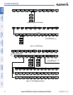
NOTE: See the Pilot’s Operating Handbook and FAA Approved Airplane Flight Manual (AFM/POH) for specific
procedures concerning avionics power application and emergency power supply operation.
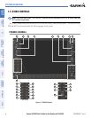
The G1000 system is integrated with the aircraft electrical system and receives power directly from electrical
busses. The G1000 PFDs, MFD and supporting sub-systems include both power-on and continuous built-in test
features that exercise the processor, RAM, ROM, external inputs and outputs to provide safe operation.
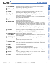
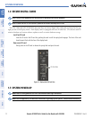
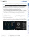
During system initialization, test annunciations are displayed, as shown in Figure 1-7. All system annunciations
should disappear typically within one minute of power-up. Upon power-up, key annunciator lights also become
momentarily illuminated on the audio panels, the control units and the display bezels.
On the PFD, the AHRS begins to initialize and displays ‘AHRS ALIGN: Keep Wings Level’. The AHRS should
display valid attitude and heading fields typically within one minute of power-up. The AHRS can align itself both
while taxiing and during level flight.
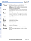
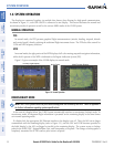
When the MFD powers up (Figure 1-8), the MFD Power-up Page displays the following information:
• System version
• Copyright
• Land database name and version
• Terrain database name and version
• Airport Terrain database name and version
• Obstacle database name and version
• Aviation database name, version, and effective dates
• ChartView or FliteCharts database information
• Safe Taxi database information
Current database information includes the valid operating dates, cycle number and database type. When this
information has been reviewed for currency (to ensure that no databases have expired), the pilot is prompted to
continue. Pressing the
ENT
Key
acknowledges this information and displays the Navigation Map Page.
Figure 1-8 MFD Power-up PageFigure 1-7 PFD Initialization