


INSTALLING THE AT10.1
4
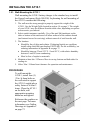
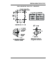
1.5.1. Wall-Mounting the AT10.1
Wall-mounting the AT10.1 battery charger is the standard way to install
the Group I enclosures (Style-586/594). In planning for wall mounting of
the AT10.1 consider the following:
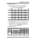
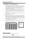
1. The wall must be strong enough to properly support the weight of the
AT10.1. See the Weight Table located in section 1.4 on page 3. The weight
of your AT10.1 may be different from the table value, depending on options
or accessories you ordered.
2. Select conduit entrances carefully. Use of the pref-fab knockouts on the
sides or bottom of the enclosure will allow removal of the cabinet shroud
(and internal access for servicing) without removal of unit from the wall.
3. The location:
• Should be free of drips and splatter. If dripping liquids are a problem,
install a drip shield kit (part number EI0191-00). For kit availability, see
ordering information in Appendix B on page 71.
• Should be between 32 and 122 °F / 0 and 50 °C, with relative humidity
between 5 and 95% non-condensing.
• Must be free of explosive materials.
4. Maintain at least 6in / 152mm of free air on top, bottom and both sides for
cooling air.
5. Allow 36in / 914mm front clearance for operation and maintenance.
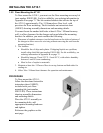
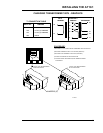
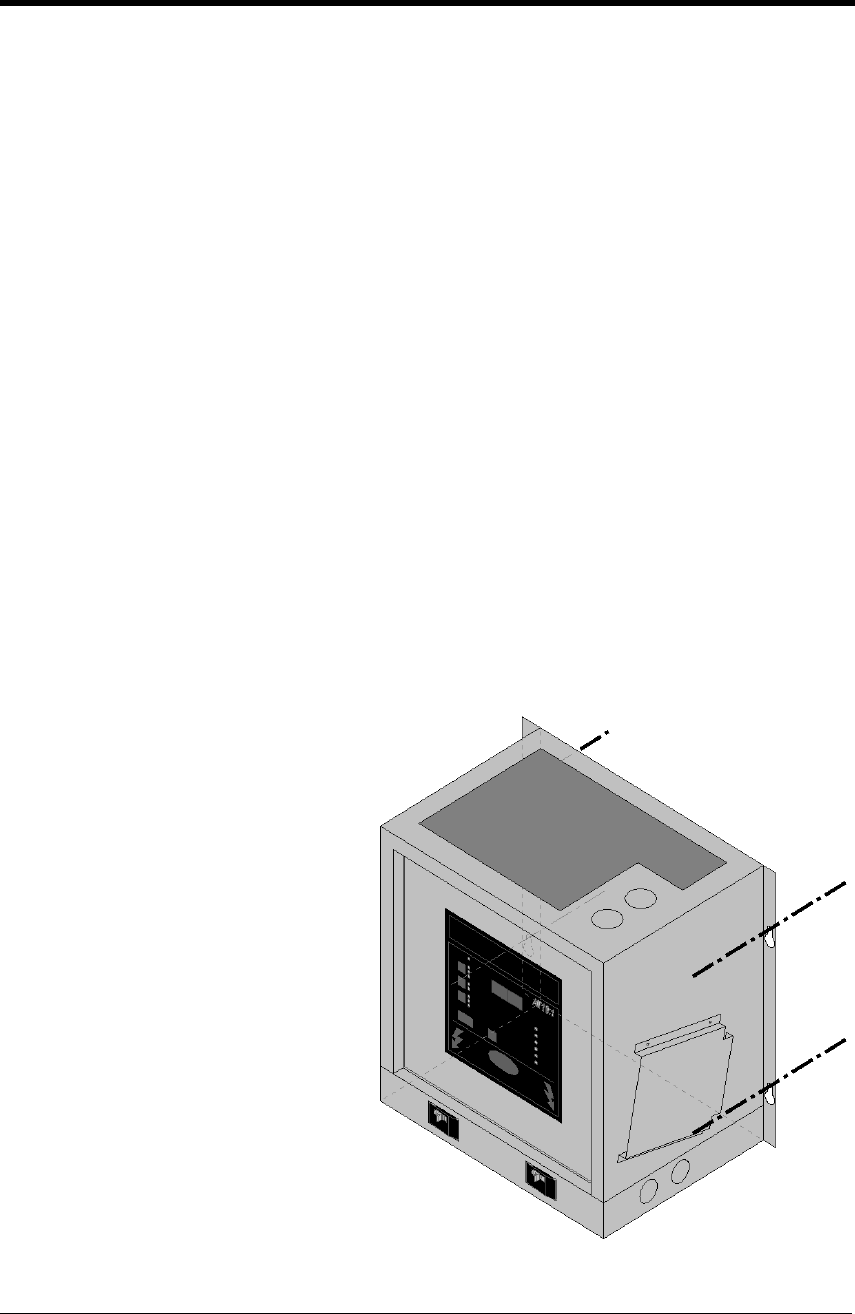
PROCEDURE
To wall-mount the
AT10.1, install four (4)
.25in / 6.4mm bolts on
the wall rated to support
the AT10.1 weight plus a
safety factor of at least 2
times. Place the AT10.1
on the bolts, add
appropriate mounting
hardware and tighten.
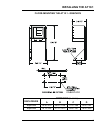
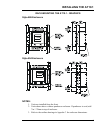
Reference the graphics on
the next page. For more
information, see Outline
Drawings in Appendix C
on page 72.