


SERVICING THE AT10.1
63
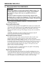
Replacing the scaling resistor (R4)
Locate the scaling resistor R4 on TB5 on the back of the front panel, just
above the control circuit board. The resistor (R4 is the one on the left) is
mounted on two quick-connect terminals. Remove the resistor by grasping
the terminals by the plastic insulation, and pulling out and downward.
Install the replacement resistor by pushing the terminals firmly onto the
quick-connect blades on the terminal block.
Replacing the voltage crowbar resistor (R6)
Locate the resistor R6 on TB5 on the back of the front panel, just above
the control circuit board. The resistor (R6 is the one on the right) is
mounted on two quick-connect terminals. Remove the resistor by grasping
the terminals by the plastic insulation, and pulling out and downward.
Install the replacement resistor by pushing the terminals firmly onto the
quick-connect blades on the terminal block.
Replacing the scaling resistor (R14)
Turn off all power to the charger. Disconnect the battery from the output
terminals. Remove the safety shield.
The scaling resistor R14 is connected to TB(-) with a ring lug. The other
lead of the resistor is soldered to wire # 20.
Remove the insulating sleeving from the soldered joint to wire # 20 (you
may have to remove a harness tie) and cut the resistor lead near the solder
joint. Disconnect the lugged-end of R14 from TB1(-) and discard the old
resistor.
Using a soldering iron no larger than 35 Watts, solder the bare lead of the
new R14 to wire # 20. Insulate the joint with plastic electrical tape. Crimp
a similar ring lug to the other lead of the new resistor. Connect the lugged
end of the new scaling resistor R14 to TB1(-).