


SERVICING THE AT10.1
55
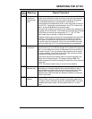
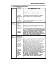
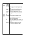
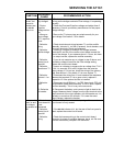
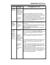
SYMPTOM
PROBABLE
CAUSE
RECOMMENDED ACTION
HIGH DC
VOLTAGE
indicator is on
1. High DC
Voltage alarm
and Equalize
voltage settings
are mismatched
2. Defective
rectifier bridge
3. Defective
control circuit
board A1
1. Be sure that the High DC Voltage alarm setting is higher
than the Equalize voltage setting. See sections 2.3.2 and
2.3.4.
2. Disconnect wire # 24 from terminal E3 of the rectifier
assembly (near the left front of the enclosure). Restart the
charger. If You are able to measure output current, one of the
SCRs is defective. Replace the rectifier assembly.
3. Turn off both front panel circuit breakers. Then turn on the
dc breaker, followed by the ac breaker. If the charger output
voltage is normal, but the HIGH DC VOLTAGE indicator is still
on, replace the control circuit board.
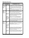
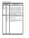
No alarm, but
output
voltage is
above High
DC Voltage
setting
1. Output
current is below
2%
2. Defective
control circuit
board A1
1. Output current must be greater than 2% of rated current to
produce a High DC Voltage alarm. See Parallel Operation in
section 2.3.6.
2. Turn off both front panel circuit breakers. Then turn on the
dc breaker, followed by the ac breaker. If the charger output
voltage is above the alarm setting, but the
HIGH DC VOLTAGE indicator still doesn't light, replace the
control circuit board.
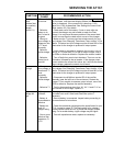
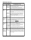
LOW DC
VOLTAGE
indicator is
on, but ac
and dc
breakers are
closed; ac
input voltage
is normal;
there is
output current
1. Battery is
discharged
2. Low DC
Voltage alarm
and Float
voltage settings
are mismatched
3. Defective
rectifier bridge
4. Defective
control circuit
board A1
5. Defective dc
breaker
1. After an ac power failure, or a battery discharge for any
other reason, it may take several hours to recharge the
battery. It is normal for the LOW DC VOLTAGE indicator to be
on until the battery voltage is above the Low DC Alarm
voltage.
2. Be sure that the Low DC Voltage alarm setting is lower than
the Float voltage setting. See sections 2.3.2 and 2.3.4.
3. Use a clamp-on ammeter to measure the current in wire #
11 or # 12. If it less than 70% of the dc output current, one of
the SCRs or diodes is defective. Replace the rectifier
assembly.
4. Turn off both front panel circuit breakers. Then turn on the
dc breaker, followed by the ac breaker. If the charger output
voltage is normal, but the LOW DC VOLTAGE indicator is still
on, replace the control circuit board.
5. Disconnect the battery, and connect a light dc load to the
charger. Measure the dc voltage from the input terminal to the
output terminal of the circuit breaker, with the breaker on. It is
normally no more than 50 millivolts. If it is near the rated
output voltage, replace the breaker.