


SERVICING THE AT10.1
57
SYMPTOM
PROBABLE
CAUSE
RECOMMENDED ACTION
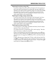
POS GND or
NEG GND
indicator is on
1. Ground fault
on external dc
bus
2. Ground
detection circuit
needs
calibration
3. Defective
wiring
4. Defective
control circuit
board A1
1. Disconnect the charger from the battery and dc bus, and
check the battery and dc bus for a ground fault.
2. Calibrate the ground detection sensitivity. See section 2.3.4.
3. Disconnect the charger from the battery and dc bus. Turn
the charger on, and measure the voltage from TB1(+) to
chassis, and from TB1(-) to chassis. The voltage readings
should be equal, each approximately half of the total output
voltage. If there is more than a 10% imbalance, turn off the
charger, and inspect all wiring from TB1 to CB2, the optional
dc filter, L1, and the rectifier bridge. Look for evidence of
insulation damage, insufficient spacing between terminals and
chassis, or wires run too close to metal edges.
4. Turn off both front panel circuit breakers. Then turn on the
dc breaker, followed by the ac breaker. If you are sure there is
no ground fault on the external bus or within the charger, but
the POS GND or NEG GND indicator is still on, replace the
control circuit board.
Summary
alarm relay is
in alarm
mode, but no
front panel
alarm
indicator is on
1. Defective
control circuit
board A1
1. Turn off both front panel circuit breakers (or turn off ac and
dc power externally if the charger doesn’t have breakers).
Then turn on the dc breaker, followed by the ac breaker. If the
relay remains in alarm mode, check the Low Level Detect
indicator on main control board. See section 2.3.8. If no other
alarm is on, replace the control circuit board.