


SERVICING THE AT10.1
51
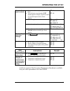
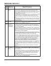
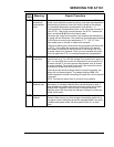
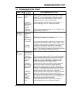
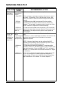
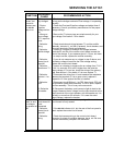
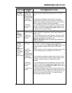
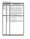
SYMPTOM
PROBABLE
CAUSE
RECOMMENDED ACTION
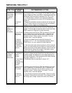
No output
current, but
ac and dc
breakers are
on; AC ON
lamp is on
1. Battery is
fully charged
2. Float or
Equalize
voltage set too
low
3. Wrong ac
input voltage,
or T1 taps mis-
wired
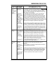
4. Defective
wiring
5. Defective
rectifier bridge
6. Defective
control circuit
board A1
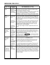
7. Defective
transformer T1
8. Defective
inductor L1 or
L2
9. Defective
CR2
10. Defective
dc breaker
1. This is normal operation in a system with little or no dc load.
As long as the charger maintains Float voltage, it is operating
normally.
2. Check the Float and Equalize voltages and adjust them if
necessary. Consult your battery manufacturer for the proper
voltage settings.
3. Be sure the T1 primary taps are wired correctly for your
input voltage. See section 1.6 for details.
4. Check terminals and wiring between T1 and the rectifier
assembly, inductor L1, dc filter (if present), the dc breaker, and
the output terminals. Repair as necessary.
5. Use an ac voltmeter to measure the voltage between
terminals E3 and E4 of the rectifier circuit board nearest the
front of the charger. If you measure about 1.0 Vrms, but there
is no output current, replace the rectifier assembly.
6. If you do not measure any ac voltage in step 5 above, and
the battery voltage is less than the Float voltage setting,
replace the control circuit board.
7. Use an ac voltmeter to measure the ac voltage from T1-X1
to X4. It is normally 50% to 80% higher than the rated dc
output voltage. If it is too low, check the wiring of the primary
taps. See section 1.6 for details. If it is zero, replace T1.
8. Disconnect the wiring from L1 and measure the resistance
between the terminals. If it is an open circuit, replace L1.
Repeat for L2 if the optional dc filter is installed.
9. Disconnect wire # 52 from L1 to CR2, then check CR2 with
an Ohmmeter (check both polarities). If CR2 is open, replace
the filter assembly. This is a very rare occurrence.
10. Disconnect the battery, and connect a light dc load to the
charger. Measure the dc voltage from the input terminal to the
output terminal of the circuit breaker, with the breaker on. It is
normally no more than 50 millivolts. If it is near the rated
output voltage, replace the breaker.
Front panel is
dead; ac and
dc voltages
are present at
TB1
1. Control
circuit board A1
is not
connected
2. Defective
control circuit
board A1
3. Defective
wiring
1. Make sure the connector at the top edge of the control
circuit board is firmly seated.
2. If the AC ON indicator is lit, but the rest of the front panel is
dead, replace the control circuit board.
3. Check the harness wiring to the control circuit board
connector for signs of insulation damage, burns, etc. Be sure
all wires are securely crimped in the connector.