


INSTALLING THE AT10.1
12
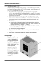
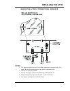
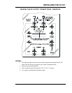
1.7. MAKING THE AC INPUT CONNECTIONS
Follow these steps to connect ac power to the AT10.1:
1. Use a branch circuit breaker or fused disconnect switch, properly sized for
the maximum input current of the AT10.1, as shown in the table below. This
device should have lockout capability so that the ac input can be de-
energized and locked out for maintenance. A time delay circuit breaker or
slow-blow fuse is recommended.
2. Size the ac input wiring per the National Electric Code (NEC) and local
codes for the rating of the branch circuit breaker or fused disconnect switch.
3. All specific requirements of your facility take precedence over these
instructions.
4. Be sure the AT10.1 main transformer, T1, is properly connected for your ac
input voltage. See section 1.6 for details.
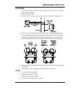
5. Remove the safety cover.
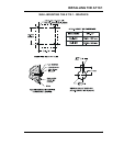
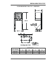
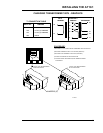
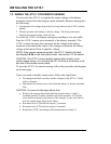
6. Run the ac wiring to terminals TB1-L1, TB1-L2 and TB1-GND on the I/O
panel in the enclosure. Compression lugs accepting wire sizes #14-6 AWG.
wire are supplied for your convenience. To make these connections, strip the
insulation .50in / 13mm on the incoming wires and connect the wires to the
appropriate lugs as shown on the next page.
7. Using a flat-head screwdriver, securely tighten the compression screws on
the lugs to 35-45 in-lb / 4.0-5.1 Nm.
8. Reinstall the safety cover after you have made and checked all connections.
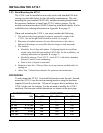
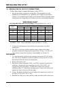
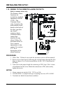
Example (shaded):
A 130 Vdc/12 Adc
battery charger
draws 30 Aac at
120 Vac.
All currents shown
are ±10%.
MAXIMUM INPUT CURRENT AT 120 Vac
1
OUTPUT VOLTAGE
OUTPUT
CURRENT
12 24 48 130
6
2 4 8 14
12
3 7 14
30
16
4 9 18 32
20
5 11 23 39
25
6 14 29 49
1
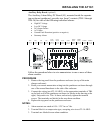
To determine the input current, I
ac
, for other input voltages, use the formula:
ac
Tac
V
II
120
×=
where V
ac
is the new input voltage, and I
T
is the input current from the table above.