


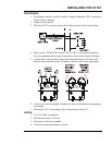

INSTALLING THE AT10.1
22
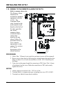
7. Check your work. Be sure that:
• All connections are secure.
• The shield is connected to ground at the charger end only (on the main
circuit board).
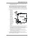
• The cable is connected to TB8 on the circuit board. Other terminal
blocks may look similar.
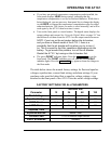
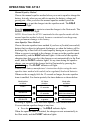
8. Restart the AT10.1 using the startup procedure in section 2.1. During
startup, the AT10.1 displays LEAD on the front panel, indicating that the
temperature compensation is set up for lead-acid batteries. While this is
being displayed, you can press any front panel key to change the display to
read NICD, to change the temperature compensation setup for nickel
cadmium batteries. The choice you make is saved internally, and will be
used again by the AT10.1 the next time it starts.
9. Adjust the output float and equalize voltages to the battery manufacturer's
recommended values, using the AT10.1's front panel meter, as described in
section 2.3.2.
NOTE: If the temperature compensation probe, or the wiring
from the probe to the AT10.1, is damaged and becomes an
open circuit, the AT10.1 detects the damage and displays
E 08 on the display. The charger then reverts to normal non-
temperature-compensated operation until the probe or wiring
is repaired. Once the probe is repaired, you must restart the
AT10.1 to activate the probe, as described in section 2.1.
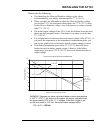
Using temperature compensation
Whenever an electric storage battery is being charged, the terminal
voltage of the battery changes a small amount whenever the battery
temperature changes. As the battery temperature increases, its terminal
voltage decreases. When the battery is being charged with a float type
charger, with a constant output voltage, the float current increases when
the temperature increases. This results in overcharging the battery, which
can result in damage to the materials, or at least the need for more
frequent maintenance.
When the AT10.1 is equipped with a temperature compensation probe, it
is able to adjust the output voltage applied to the battery to keep the float
current constant, thereby avoiding overcharging. The probe senses the
ambient temperature at the battery, and adjusts the output float/equalize
voltages to compensate for variations in temperature. If the ambient
temperature increases, the AT10.1 output voltage decreases.