


INSTALLING THE AT10.1
20
1.11. INSTALLING TEMP. COMPENSATION ASSEMBLY (OPTIONAL)
The temperature compensation assembly consists of a probe containing a
temperature-dependent resistor in an epoxy module that you install near
your battery. There are three steps in installing the assembly:
1. Mounting the probe assembly near the battery.
2. Installing an interconnection cable from the probe assembly to the AT10.1.
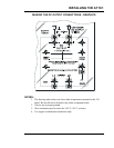
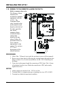
3. Wiring the charger end of the cable to a terminal block on the main control
circuit board.
The actual tempco probe is the same for all battery types and all output
voltages of the AT10.1. The kit part numbers differ depending on cable
length ordered. See the tables in Appendix B on page 71 for ordering
information. Each kit contains detailed installation instructions (JA5015-
00). The main elements of the installation are outlined below.
WARNING:
High voltages appear at several points inside the battery charger. Use
extreme caution when working inside the charger. Do not attempt to
work inside the charger unless you are a qualified technician or
electrician.
Disconnect and lock out all power to the battery charger before starting
to remove or replace any components. Turn the ac power off at the
distribution panel upstream from the battery charger. Disconnect the
battery from the charger output terminals.
1. De-energize and lock out all ac and dc voltage sources to the AT10.1. Check
with a voltmeter before proceeding.
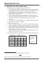
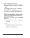
2. Mount the probe on a clean, dry surface as close to the battery as possible,
such as the battery rack. Do not mount the probe:
• on the battery itself
• on unpainted wood or bare galvanized metal.
• on plastic surfaces
3. To apply the probe, clean the mounting surface with isopropyl alcohol, and
allow to dry thoroughly. Remove the protective backing from the double-
faced adhesive tape on the probe, and securely press it onto the surface.
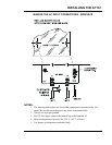
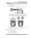
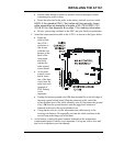
4. Install the cable supplied with the temperature compensation probe kit:
• Start at the AT10.1. The end of the cable with two stripped wires and one
lead with a quick-connect terminal will be connected inside the
enclosure. Leave 30in / 762mm of cable inside the enclosure, and route
the other end to the probe at the battery.