


SERVICING THE AT10.1
49
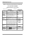
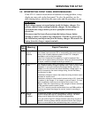
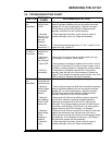
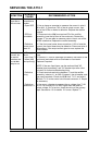
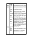
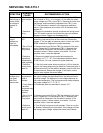
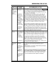
3.4. TROUBLESHOOTING CHART
SYMPTOM
PROBABLE
CAUSE
RECOMMENDED ACTION
AC breaker
trips
immediately
1. Shorted
rectifier diode
or SCR
2. Defective
wiring to T1 or
to the rectifier
heat sink
assembly
3. Defective
transformer T1
1. Test by disconnecting wire # 12 from the rectifier assembly.
Measure resistance between the two top rectifier terminals
(labeled "AC" on the wiring diagram); it should be at least
100,000 Ohms (check both polarities). Replace rectifier
assembly if resistance is low in either direction.
2. Check spacing of terminals; check wiring for signs of
insulation damage, burns, etc. Repair as necessary.
3. Test by disconnecting wires from X1, X4, Y1 and Y2. If ac
breaker still trips, replace T1.
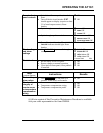
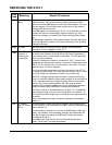
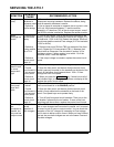
AC breaker
trips after a
few minutes
1. Loose
connection to
breaker
2. Wrong ac
voltage, or T1
taps miswired
3. Open SCR
4. SCR not
controllable
1. Check and tighten connections as required.
2. Be sure the T1 primary taps are wired correctly for your
input voltage. See section 1.6 for details.
3. Use a clamp-on ammeter to measure the current in wire #
11 or # 12. If it less than 70% of the dc output current, one of
the SCRs or diodes is defective. Replace the rectifier module.
4. Disconnect wire # 24 from terminal E3 of the rectifier
assembly (near the left front of the enclosure). Restart the
charger. If You are able to measure output current, one of the
SCRs is defective. Replace the rectifier assembly.
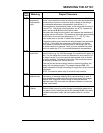
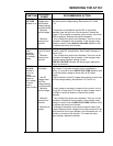
DC breaker
trips
immediately
1. Battery
connected with
reverse polarity
2. Defective
rectifier bridge
(if unfiltered
charger)
3. Defective
free-wheeling
diode in SCR
module A16
4. Defective
polarity diode
(if filter
assembly is
installed)
5. Defective
wiring
1. Check and correct battery wiring if necessary.
2. Test by disconnecting wire # 12 from the rectifier assembly.
Measure resistance between the two top rectifier terminals
(labeled "AC" on the wiring diagram); it should be at least
100,000 Ohms (check both polarities). Replace rectifier
assembly if resistance is low in either direction.
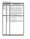
3. Remove wire # 13 from the rectifier control pc board A3.
Test the SCR module's internal free-wheeling diode by
measuring the resistance from E2 to E10 on A3 with an
Ohmmeter. The reading should be at least 100,000 Ohms in
one polarity, and less than 1,000 Ohms in the other polarity.
Replace the entire A16 SCR module if it is defective.
4. Remove wire # 15 from terminal E14 on the CR1 heat sink.
Measure the resistance from the heat sink to E8 on the
rectifier control pc board at the left front of the charger (check
both polarities). If the resistance is less than 1,000 Ohms in
both directions, replace the filter assembly.
5. Check spacing of terminals; check wiring for signs of
insulation damage, burns, etc. Repair as necessary.