


OPERATING THE AT10.1
26
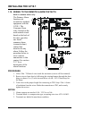
2.2. USING THE AT10.1 FRONT PANEL FEATURES
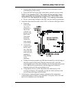
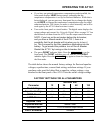
2.2.1. If the meter displays an error message
When you apply power to the AT10.1 for the first time, the micro-
processor control circuit performs a diagnostic check of the system. If it
finds anything wrong, it writes an error code to the display, such as E 01.
Below is a list of the error codes. See section 3.2 for a full explanation of
each error code.
Error Code Explanation
E 01
Resistor R2 is open or defective.
E 02
Short circuit on output
E 03
HVDC Shutdown has occurred
E 04
Internal memory failure
E 05
Not used
E 06
Failure in Remote Sense wiring
E 07
DC breaker is open, or internal or external
output wiring is defective.
E 08
Defective temperature compensation probe
E 09
Misadjusted current limit
E 10
Open internal feedback loop
A 02
Equalize mode is inhibited
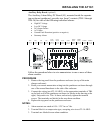
2.2.2. Selecting the meter mode
• Press the METER MODE key to change the meter display mode. The digital
meter has four operating modes:
1. Alternating between output voltage and output current. When the
charger is in a timed equalize mode, the meter alternates between
output voltage, output current, and equalize hours remaining.
2. Displaying output voltage only. The DC Volts indicator lights.
3. Displaying output current only. The DC Amps indicator lights.
4. Displaying equalize hours remaining only. The EQLZ HRS
REMAINING indicator lights. If the AT10.1 is not in a timed
equalize mode, the meter displays the full programmed equalize
time.
• When the charger starts initially, the meter alternates, showing output
voltage and output current. The DC Volts and DC Amps indicators light
alternately to indicate what is being displayed.