


OPERATING THE AT10.1
29
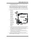
2.2.5. Testing the front panel indicators
• Press the DOWN key. This is also the LAMP TEST key.
The meter will display 8888, and all status & alarm indicators will light.
The LAMP TEST key does not test the AC ON indicator. The AC ON
indicator lights whenever ac power is present, and the ac circuit breaker is
turned on. The LAMP TEST key does not operate when ac power is off.
To test the action of the summary alarm relay, press and hold the
LAMP TEST key for four seconds. The relay transfers. If you are monitoring
the relay with a remote annunciator, it detects the alarm condition.
2.2.6. Testing the Auxiliary Relay Board (optional)
If you have the optional Auxiliary Relay Board installed, you can test the
action of the alarm relays. Press and hold the LAMP TEST key for four
seconds. The six auxiliary alarm relays on the Auxiliary Relay Board
transfer. Remote annunciators connected to these relays will indicate this.
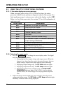
2.2.7. Interpreting the alarm indicators
There are six alarm indicators at the right side of the front panel. An
indicator lights for each of the following alarm conditions:
• HIGH DC VOLTAGE: lights whenever the dc output voltage exceeds
the specified alarm voltage setting. See section 2.3.4 to learn how to
adjust the HVDC alarm setting.
• LOW DC VOLTAGE: lights whenever the dc output voltage is below
the specified alarm voltage setting. See section 2.3.4 to learn how to
adjust the LVDC alarm setting.
• DC OUTPUT FAILURE: lights whenever the charger cannot provide
its full rated output voltage or its full rated output current. You cannot
adjust this alarm setting.
• AC INPUT FAILURE: lights whenever the ac power supply to the
charger is interrupted.
• POS GND: lights whenever leakage current from the battery positive
terminal to ground exceeds a specified threshold (see note).
• NEG GND: lights whenever leakage current from the battery negative
terminal to ground exceeds a specified threshold (see note).
NOTE: You can adjust the sensitivity of the ground fault detection
from 5K to 50k ohms. Adjusting the ground fault sensitivity affects
the positive and negative ground fault sensitivities equally.
The indicators light immediately when an alarm occurs. The AT10.1 also
has a summary alarm relay with one form C contact, rated 0.5A @ 125
Vac/Vdc. If an alarm condition lasts for 30 seconds or longer, the
summary alarm relay contact transfers. When the alarm condition is
corrected, the relay and all indicators reset automatically.