


SERVICING THE AT10.1
54
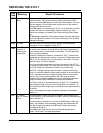
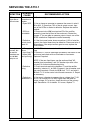
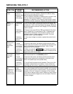
SYMPTOM
PROBABLE
CAUSE
RECOMMENDED ACTION
Charger very
noisy
1. Loose
hardware or
enclosure panel
2. Defective
rectifier bridge
1. Remove the enclosure shroud. Check and tighten all
component mounting hardware. Replace the shroud, being
sure all assembly hardware is secure.
2. Use a clamp-on ammeter to measure the ac current in wire
# 11 or # 12 (connected between T1 and the rectifier
assembly). If it less than 70% of the dc output current, one of
the SCRs or diodes is defective. Replace the rectifier module.
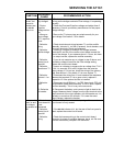
Meter
readings are
erratic
1. Defective or
disconnected
battery
2. Defective
scaling resistor
R4 or R14
3. Defective
control circuit
board A1
1. Turn off the charger. With a light dc load connected to the
battery, be sure each cell reads the nominal cell voltage (2.0V
for lead-acid; 1.25V for Ni-Cd). Restart the charger. Each cell
should now read the nominal Float voltage (2.2V for lead-acid;
1.35V for Ni-Cd).
2. Remove one end of R4 from TB5 (on the back of the front
panel). Repeat for R14 connected to TB1(-). Measure their
values with an Ohmmeter. See the table in section 3.6 for
resistance values. If either resistor is not within 1% of the
specified value, it must be replaced.
3. If the output voltage is constant, replace the control circuit
board.
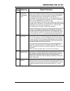
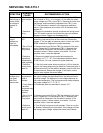
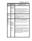
Lamp test key
doesn't work,
or some
lamps don't
light
1. No Vac
2. Control
circuit board A1
is not secured
to front panel
3. Defective
control circuit
board A1
1. The lamp test key doesn’t work during an ac power failure.
2. Open the front panel, and be sure that the control circuit
board is securely mounted on the standoffs on the back of the
panel. All indicators should extend about .125in / 3.2mm
through the front of the panel.
3. When you press the LAMP TEST key, if some but not all of
the indicators light, or the digital meter does not display all 8's,
replace the control circuit board.
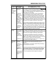
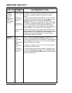
One or more
front panel
keys don't
work
1. Front panel
is locked
2. Control
circuit board A1
is not secured
to front panel
3. Defective
control circuit
board A1
1. Open the front panel, and be sure that jumper J9 on the
main control board is in the ENABLE position.
2. Open the front panel, and be sure that the control circuit
board is firmly seated on the standoffs on the back of the
panel. Front panel keys must operate freely.
3. Turn off both front panel circuit breakers. Then turn on the
dc breaker, followed by the ac breaker. If some of the front
panel keys still do not work, replace the control circuit board.
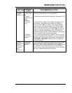
Two chargers
are
connected in
parallel, but
only one has
output current
1. Check for
normal
operation of
both chargers
1. The AT10.1 is not designed to share the load current when
two or more chargers are connected in parallel, so it is normal
for one of a pair to have no output current. You can check the
operation of the "off" charger by increasing its Float voltage
until it starts to deliver output current. When you have finished
the test, be sure both chargers are set to the same Float and
Equalize voltages.