


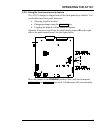
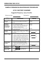

SERVICING THE AT10.1
47
Error
Code
Meaning Repair Procedure
E 08
Defective
temperature
compensation
probe
If a temperature compensation probe is connected to the AT10.1, the
control circuit detects the probe on startup, and uses the temperature
measured by the probe to control the output voltage of the charger.
To understand temperature compensation, see section 1.11.
If the temperature compensation probe, or the wiring that connects it
to the AT10.1, fails during normal operation, the AT10.1 detects the
failure, and shows E 08 on the front panel meter.
Disconnect the wiring from the probe, and measure the resistance of
the probe with an Ohmmeter. The resistance should be approximately
10,000 Ohms at normal room temperature (77° F / 25° C). If the
probe reads open or shorted, it needs to be replaced.
If the probe checks good, examine the wiring between the probe and
the AT10.1. Also check the connection of the cable to the control
circuit board on the back of the front panel. If the wiring is OK, then
the probe needs to be replaced. Once you have replaced the probe,
you must restart the AT10.1 to activate temperature compensation.
E 09
Misadjusted
current limit
The output current limit is set at the factory to 110% of the rated
output current (e.g., for a 20 Adc charger, the current limit is set to 22
Adc). You can adjust the current limit downward to as low as 50% of
the output current, if you have special requirements such as limited
ac power available. You should do this only if the normal dc load on
the system is smaller than the current limit.
If the load current becomes larger than the current limit setting, the
battery will not charge properly. The charger displays E 09. You
should increase the current limit setting to supply the current required
by the load.
NOTE: The common alarm relay is not set for this condition.
E 10
Open internal
feedback loop
A redundant internal feedback loop (control loop) is provided as
redundancy, to increase reliability when remote sensing is used. If
there should be a problem with the internal loop wiring, the charger
displays E 10. Check the internal wiring in the signal harness,
especially wire # 33. Also check the harness connector on the main
control circuit board.
A 02
Equalize mode
inhibited
If you set the equalize timer to zero hours, the equalize mode is
inhibited. When you try to put the charger into equalize mode with a
front panel control, the display shows the message A 02. If you want
to enable the equalize mode, set the equalize timer to 1 or more
hours.