


OPERATING THE AT10.1
38
2.3.8. Using the Low Level Detector (LLD)
The AT10.1 charger is equipped with a summary alarm safety override
circuit. This safety feature forces the summary alarm (common alarm)
relay contact to transfer, sending an alarm, even if there is a catastrophic
failure of the control circuitry. A low battery voltage triggers the safety
circuit.
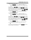
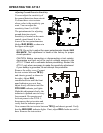
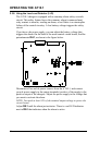
If you have a dc power supply, you can adjust the battery voltage that
triggers the alarm. On the back of the main control circuit board, find the
potentiometer RA1, as shown in the figure below.
Disconnect all ac and dc power sources from the AT10.1, and connect
your dc power supply to the output terminals (positive of the supply to the
positive output of the charger). Adjust the power supply to the voltage that
you want to activate the alarm.
NOTE: You need at least 50% of the nominal output voltage to power the
circuit board.
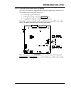
Adjust RA1 until the alarm just activates. There is a red LED indicator
next to RA1 that indicates when the alarm is active.