


SERVICING THE AT10.1
45
3.2. INTERPRETING FRONT PANEL ERROR MESSAGES
If the AT10.1 control circuit detects a hardware or wiring problem, it may
display an error code on the front panel. To solve the problem, use the
table starting below, which lists the error codes and the procedures to use.
WARNING:
High voltages appear at several points inside the battery charger. Use
extreme caution when working inside the charger. Do not attempt to
work inside the charger unless you are a qualified technician or
electrician.
Disconnect and lock out all power from the battery charger before
starting to remove or replace any components. Turn the ac power off at
the distribution panel upstream from the battery charger. Disconnect the
battery from the charger output terminals.
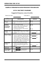
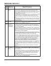
Error
Code
Meaning Repair Procedure
E 01
Resistor R2
open or
defective
Resistor R2 is installed at the back of the front panel, in the control
circuit board input connector. R2 is measured by the control circuit on
startup, and is used to determine some of the AT10.1 charger's
parameters, such as the float voltage.
If the AT10.1 finds that R2 is defective, it must be replaced. See
section 3.6 for parts ordering information. When you have completed
the repair, restart the charger according to section 2.1.
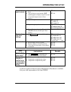
E 02
Short circuit on
output
You may get this error code if the battery is discharged to less than 6
volts. When the battery charges to greater than 6 volts, the error code
disappears. If you have a seriously discharged battery, allow the
charger to run for 24 hours and check the battery voltage again. If it
has not increased to the normal voltage rating, consult the battery
manufacturer for help.
If the battery voltage is normal, then check the wiring at the dc output
terminals for a short circuit.
If the battery voltage is normal and all external wiring is OK, check the
dc breaker on the charger. If it is tripped, try once to reset it. If it trips
again immediately, there may be an internal short circuit in the
charger. Check the internal wiring. If the charger is filtered, check the
dc filter capacitors and the polarity diode.
The AT10.1 normally recovers automatically from an E 02 condition. If
you have shut down the charger for service, restart it according to
section 2.1.
E 03
High DC
Voltage
Shutdown
To restart the charger, turn the ac breaker off, then on. Check the
Equalize voltage and High DC Voltage alarm settings. The alarm
setting must be higher than the Equalize voltage setting.
If you get another High DC Voltage shutdown after a few minutes of
operation, there may be an internal component failure. See Charger
output not controllable of the troubleshooting chart in section 3.4.